

主题中讨论的其他器件: EVM430-FR6047
您好!
使用8MHz HFX 振荡器和32.168KHz LFx 振荡器
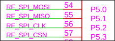
具有以下引脚且使用 USCI_A2
我正在使用的同一代码是、
#包含
Volatile unsigned char RXData = 0;
Volatile unsigned char TXData;
int main (空)
{
WDTCTL = WDTPW | WDTHOLD; //停止看门狗计时器
//配置 GPIO
P5SEL1 &=~(BIT2 | BIT0 | BIT1 | BIT3); // USCI_A2 SCLK、MOSI、MISO、CS 引脚
P5SEL0 |= BIT2 | BIT0 | BIT1 | BIT3;
PJSEL0 |= BIT4 | BIT5; //表示 XT1
//禁用 GPIO 上电默认高阻抗模式以激活
//先前配置的端口设置
PM5CTL0 &=~μ A LOCKLPM5;
// XT1设置
CSCTL0_H = CSKEY_H; //解锁 CS 寄存器
CSCTL1 = DCOFSEL_0; //将 DCO 设置为1MHz
CSCTL1 &=~μ V DCORSEL;
CSCTL2 = SELM__LFXTCLK | SELS__DCOCLK | SELM__DCOCLK;
CSCTL3 = DIVA__1 | DIVS__1 | DIVM__1; //设置所有分频器
CSCTL4 &=~LFXTOFF;
正确
{
CSCTL5 &=~LFXTOFFG; //清除 XT1故障标志
SFRIFG1 &=~OFIFG;
}while (SFRIFG1和 OFIFG); //测试振荡器故障标志
CSCTL0_H = 0; //锁定 CS 寄存器
//针对 SPI 操作配置 USCI_A2
UCA2CTLW0 = UCSWRST; //**将状态机置于复位状态**
// 4引脚8位 SPI 主设备
UCA2CTLW0 |= UCMST | UCSYNC | UCCKPL | UCMSB | UCMODE_1 | UCSTEM;
//时钟极性高,MSB
UCA2CTLW0 |= UCSSEL_ACLK; // ACLK
UCA2BRW = 0x02; ///2
UCA2MCTLW = 0; //无调制
UCA2CTLW0 &&~UCSWRST; //**初始化 USCI 状态机**
TXData = 0x1; //保存 TX 数据
while (1)
{
UCA2IE |= UCTXIE;
__ bis_SR_register (LPM0_bits | GIE);//输入 LPM0、启用中断
__ no_operation (); //保持在 LPM0中
__delay_cycles (2000); //下一次传输之前的延迟
TXData++; //递增发送数据
}
}
在这段代码下、SPI 不传输任何数据。 有人能请热心帮忙解决这个问题吗? 代码是否正确..?
