


各位专家、您好!
我的板基于 SDK 8.0、主 SDHCSI2与 SDIO WIFI 模块相连、连接方式为
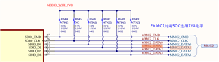
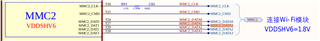
如上所示、我们未连接 MMC_CD 引脚、因为 WiFi 模块不提供 MMC_CD 引脚。 但我们打印了终端:
[23.861342] mmc2:等待硬件 cmd 中断超时。
[23.867079] mmc2:sdhci:==== SDHCI 寄存器转储====
[23.873501] mmc2:sdhci:sys addr:0x00000000 |版本:0x00001004
[23.879923] mmc2:sdhci:blk 大小:0x00000000 | Blk cnt:0x00000000
[23.886343] mmc2:sdhci:参数:0x80000c08 | Trn 模式:0x00000000
[23.892764] mmc2:sdhci:present:0x01f20001 | Host ctl:0x00000001
[23.899186] mmc2:sdhci:power:0x0000000e | Blk GAP:0x00000080
[23.905607] mmc2:sdhci:WAKE-UP:0x00000000 |时钟:0x0000fa07
[23.912029] mmc2:sdhci:timeout:0x00000000 | int stat:0x00000000
[23.918450] mmc2:sdhci:int enab:0x00ff0003 | sig enab:0x00ff0003
[23.924871] mmc2:sdhci:acmd stat:0x00000000 |插槽内部:0x00000000
[23.931291] mmc2:sdhci:cap:0x7fe8c801 | caps_1:0x18002407
[23.937712] mmc2:sdhci:cmd:0x0000341a |最大电流:0x00000000
[23.944132] mmc2:sdhci:RESP[0]:0x00000000 | Resp[1]:0x00000000
[23.950553] mmc2:sdhci:RESP[2]:0x00000000 | Resp[3]:0x00000000
[23.956973] mmc2:sdhci:host ctl2:0x00000000
[23.961401] mmc2:sdhci:Adma Err:0x00000000 | ADMA PTR:0x0000000000000000
[23.968515] mmc2:sdhci:================================================
但是、当我将 MMC2_CD (焊球 W2)置于水泥浇注环境时、WiFi 模块正常、上面没有一项打印出来。 我的 sdhci2设备树是
我的 DTS 文件 K3-j721e-common-board.dts 是
// SPDX-License-Identifier: GPL-2.0 /* * Copyright (C) 2019 Texas Instruments Incorporated - https://www.ti.com/ */ /dts-v1/; #include "k3-j721e-som-p0.dtsi" #include <dt-bindings/gpio/gpio.h> #include <dt-bindings/input/input.h> #include <dt-bindings/net/ti-dp83867.h> #include <dt-bindings/phy/phy-cadence.h> / { chosen { stdout-path = "serial2:115200n8"; bootargs = "console=ttyS2,115200n8 earlycon=ns16550a,mmio32,0x02800000"; }; gpio_keys: gpio-keys { compatible = "gpio-keys"; autorepeat; pinctrl-names = "default"; pinctrl-0 = <&sw10_button_pins_default &sw11_button_pins_default &pps_pins_default &rtk_pins_default>; sw10: sw10 { label = "GPIO Key USER1"; linux,code = <BTN_0>; gpios = <&main_gpio0 0 GPIO_ACTIVE_LOW>; }; sw11: sw11 { label = "GPIO Key USER2"; linux,code = <BTN_1>; gpios = <&wkup_gpio0 7 GPIO_ACTIVE_LOW>; }; }; xavier-gpio { status = "disabled"; compatible = "poseidon,xavier-gpio"; pinctrl-names = "default"; pinctrl-0 = <&xavier_main_pins_default &xavier_wkup_pins_default>; xavier_power_on = <&main_gpio0 113 GPIO_ACTIVE_HIGH>; sw00 { /* gpio = <&main_gpio1>; */ gpio = <&main_gpio1 32 GPIO_ACTIVE_HIGH>; gpios = <&main_gpio1 32 GPIO_ACTIVE_HIGH>; value = <0>; }; //rst->0 sw01 { /* gpio = <&main_gpio0>; */ gpio = <&main_gpio0 114 GPIO_ACTIVE_HIGH>; gpios = <&main_gpio0 114 GPIO_ACTIVE_HIGH>; value = <0>; };//MODULE_POWER_ON->0 sw1 { gpio = <&main_gpio0 120 GPIO_ACTIVE_HIGH>; gpios = <&main_gpio0 120 GPIO_ACTIVE_HIGH>; value = <1>; };//POWER_BT_N sw2 { /* gpio = <&main_gpio0>; */ gpio = <&wkup_gpio0 37 GPIO_ACTIVE_LOW>; gpios = <&wkup_gpio0 37 GPIO_ACTIVE_LOW>; value = <0>; };//VSYS_12V_EN sw3 { /* gpio = <&main_gpio0>; */ gpio = <&main_gpio0 115 GPIO_ACTIVE_HIGH>; gpios = <&main_gpio0 115 GPIO_ACTIVE_HIGH>; value = <1>; };//VIN_PWR_ON sw4 { /* gpio = <&main_gpio0>; */ gpio = <&main_gpio0 114 GPIO_ACTIVE_HIGH>; gpios = <&main_gpio0 114 GPIO_ACTIVE_HIGH>; value = <1>; };//MODULE_POWER_ON sw5 { /* gpio = <&main_gpio1>; */ gpio = <&main_gpio1 32 GPIO_ACTIVE_HIGH>; gpios = <&main_gpio1 32 GPIO_ACTIVE_HIGH>; value = <1>; };//rst->1 }; evm_12v0: fixedregulator-evm12v0 { /* main supply */ compatible = "regulator-fixed"; regulator-name = "evm_12v0"; regulator-min-microvolt = <12000000>; regulator-max-microvolt = <12000000>; regulator-always-on; regulator-boot-on; }; vsys_3v3: fixedregulator-vsys3v3 { /* Output of LMS140 */ compatible = "regulator-fixed"; regulator-name = "vsys_3v3"; regulator-min-microvolt = <3300000>; regulator-max-microvolt = <3300000>; vin-supply = <&evm_12v0>; regulator-always-on; regulator-boot-on; }; vsys_5v0: fixedregulator-vsys5v0 { /* Output of LM5140 */ compatible = "regulator-fixed"; regulator-name = "vsys_5v0"; regulator-min-microvolt = <5000000>; regulator-max-microvolt = <5000000>; vin-supply = <&evm_12v0>; regulator-always-on; regulator-boot-on; }; vdd_mmc1: fixedregulator-sd { compatible = "regulator-fixed"; regulator-name = "vdd_mmc1"; regulator-min-microvolt = <3300000>; regulator-max-microvolt = <3300000>; regulator-boot-on; enable-active-high; vin-supply = <&vsys_3v3>; /* gpio = <&exp2 2 GPIO_ACTIVE_HIGH>; */ }; /* ethernet phy mode driver for marvell 1512 */ phymode { status = "disabled"; }; /* sound0: sound@0 { compatible = "ti,j721e-cpb-audio"; model = "j721e-cpb"; ti,cpb-mcasp = <&mcasp10>; ti,cpb-codec = <&pcm3168a_1>; clocks = <&k3_clks 184 1>, <&k3_clks 184 2>, <&k3_clks 184 4>, <&k3_clks 157 371>, <&k3_clks 157 400>, <&k3_clks 157 401>; clock-names = "cpb-mcasp-auxclk", "cpb-mcasp-auxclk-48000", "cpb-mcasp-auxclk-44100", "cpb-codec-scki", "cpb-codec-scki-48000", "cpb-codec-scki-44100"; }; */ clk_fusion_25M_fixed: fixed-clock-25M { compatible = "fixed-clock"; #clock-cells = <0>; clock-frequency = <25000000>; }; hdmi-connector { compatible = "hdmi-connector"; label = "hdmi"; type = "a"; port { hdmi_connector_in: endpoint { remote-endpoint = <&tfp410_out>; }; }; }; dvi-bridge { #address-cells = <1>; #size-cells = <0>; compatible = "ti,tfp410"; /* HDMI_PDn */ pinctrl-names = "default"; pinctrl-0 = <&dvi_bridge_power_gpio_pins_default>; powerdown-gpios = <&main_gpio1 29 GPIO_ACTIVE_HIGH>; port@0 { reg = <0>; tfp410_in: endpoint { remote-endpoint = <&dpi_out0>; pclk-sample = <1>; }; }; port@1 { reg = <1>; tfp410_out: endpoint { remote-endpoint = <&hdmi_connector_in>; }; }; }; pps_gpio: pps-gpio { compatible = "pps-gpio"; pinctrl-names = "default"; pinctrl-0 = <&pps_gpio_pin_default>; gpios = <&wkup_gpio0 8 GPIO_ACTIVE_HIGH>; status = "okay"; }; cpsw9g_virt_mac: main_r5fss_cpsw9g_virt_mac0 { compatible = "ti,j721e-cpsw-virt-mac"; dma-coherent; ti,psil-base = <0x4a00>; ti,remote-name = "mpu_1_0_ethswitch-device-0"; dmas = <&main_udmap 0xca00>, <&main_udmap 0xca01>, <&main_udmap 0xca02>, <&main_udmap 0xca03>, <&main_udmap 0xca04>, <&main_udmap 0xca05>, <&main_udmap 0xca06>, <&main_udmap 0xca07>, <&main_udmap 0x4a00>; dma-names = "tx0", "tx1", "tx2", "tx3", "tx4", "tx5", "tx6", "tx7", "rx"; virt_emac_port { ti,label = "virt-port"; /* local-mac-address = [0 0 0 0 0 0]; */ }; }; transceiver1: can-phy@0 { compatible = "ti,tcan1043"; #phy-cells = <0>; max-bitrate = <5000000>; pinctrl-names = "default"; pinctrl-0 = <&mcu_mcan0_gpio_pins_default>; standby-gpios = <&wkup_gpio0 14 GPIO_ACTIVE_LOW>; enable-gpios = <&wkup_gpio0 15 GPIO_ACTIVE_HIGH>; }; /* transceiver2: can-phy@1 { compatible = "ti,tcan1042"; #phy-cells = <0>; max-bitrate = <5000000>; pinctrl-names = "default"; pinctrl-0 = <&mcu_mcan1_gpio_pins_default>; standby-gpios = <&wkup_gpio0 2 GPIO_ACTIVE_HIGH>; }; */ gobinet_pwr_on: fixedregulator-gobinet@0 { compatible = "regulator-fixed"; regulator-name = "gobinet_pwr_on"; pinctrl-names = "default"; pinctrl-0 = <&gobinet_poweron_pins_default>; regulator-min-microvolt = <3300000>; regulator-max-microvolt = <3300000>; regulator-always-on; regulator-boot-on; enable-active-high; gpio = <&main_gpio0 4 GPIO_ACTIVE_HIGH>; }; gobinet_reset: fixedregulator-gobinet@1 { compatible = "regulator-fixed"; regulator-name = "gobinet_reset"; pinctrl-names = "default"; pinctrl-0 = <&gobinet_reset_pins_default>; regulator-min-microvolt = <0>; regulator-max-microvolt = <0>; regulator-always-on; regulator-boot-on; enable-active-low; gpio = <&main_gpio0 5 GPIO_ACTIVE_LOW>; }; gobinet_flymode: fixedregulator-gobinet@2 { compatible = "regulator-fixed"; regulator-name = "gobinet_flymode"; pinctrl-names = "default"; pinctrl-0 = <&gobinet_flymode_pins_default>; regulator-min-microvolt = <3300000>; regulator-max-microvolt = <3300000>; regulator-always-on; regulator-boot-on; enable-active-high; gpio = <&wkup_gpio0 7 GPIO_ACTIVE_HIGH>; }; gobinet_gnss: fixedregulator-gobinet@2 { compatible = "regulator-fixed"; regulator-name = "gobinet_gnss"; pinctrl-names = "default"; pinctrl-0 = <&gobinet_gnss_pins_default>; regulator-min-microvolt = <3300000>; regulator-max-microvolt = <3300000>; regulator-always-on; regulator-boot-on; enable-active-high; gpio = <&main_gpio0 53 GPIO_ACTIVE_HIGH>; }; eth_pwr_ctl: fixedregulator-eth@0 { compatible = "regulator-fixed"; regulator-name = "eth_pwr_ctl"; pinctrl-names = "default"; pinctrl-0 = <ð_pwr_pins_default>; regulator-min-microvolt = <0>; regulator-max-microvolt = <0>; regulator-always-on; regulator-boot-on; enable-active-low; gpio = <&main_gpio0 7 GPIO_ACTIVE_LOW>; }; sleep_en: fixedregulator-sleepen@0 { compatible = "regulator-fixed"; regulator-name = "sleepen_ctl"; pinctrl-names = "default"; pinctrl-0 = <&sleepen_pins_default>; regulator-min-microvolt = <0>; regulator-max-microvolt = <0>; regulator-always-on; regulator-boot-on; enable-active-low; gpio = <&main_gpio0 6 GPIO_ACTIVE_LOW>; }; powerout2_pwr_en: fixedregulator-power@1 { compatible = "regulator-fixed"; regulator-name = "powerout2_on"; pinctrl-names = "default"; pinctrl-0 = <&powerout2_pins_default>; regulator-min-microvolt = <3300000>; regulator-max-microvolt = <3300000>; regulator-always-on; regulator-boot-on; enable-active-high; gpio = <&main_gpio0 108 GPIO_ACTIVE_HIGH>; }; }; &main_pmx0 { sw10_button_pins_default: sw10-button-pins-default { pinctrl-single,pins = < J721E_IOPAD(0x0, PIN_INPUT, 7) /* (AC18) EXTINTn.GPIO0_0 */ >; }; powerout2_pins_default: powerout2-pins-default { pinctrl-single,pins = < J721E_IOPAD(0x1b4, PIN_OUTPUT, 7) /* (W25) RGMII6_RD0.GPIO0_108 */ >; }; sja1105_reset_default: sja1105_reset_default { pinctrl-single,pins = < J721E_IOPAD(0x8, PIN_INPUT, 7) /* (AG22) GPIO0_2 */ >; }; spi3_pins_default: spi3_pins_default { /* TODO: */ pinctrl-single,pins = < J721E_IOPAD(0x144, PIN_INPUT, 4) /* (Y25) SPI3_CLK */ J721E_IOPAD(0x11C, PIN_INPUT, 4) /* (AA24) SPI3_CS */ J721E_IOPAD(0x148, PIN_INPUT, 4) /* (AA26) SPI3_MOSI */ J721E_IOPAD(0x14C, PIN_INPUT, 4) /* (AA29) SPI3_MISO */ >; }; spi5_pins_default: spi5_pins_default { /* TODO: */ pinctrl-single,pins = < J721E_IOPAD(0x1A0, PIN_INPUT, 3) /* (W29) SPI5_CLK */ J721E_IOPAD(0x19C, PIN_INPUT, 3) /* (W27) SPI5_CS */ J721E_IOPAD(0x198, PIN_INPUT, 3) /* (V25) SPI5_MOSI */ J721E_IOPAD(0x1B0, PIN_INPUT, 3) /* (W24) SPI5_MISO */ >; }; main_mmc1_pins_default: main-mmc1-pins-default { pinctrl-single,pins = < J721E_IOPAD(0x254, PIN_INPUT, 0) /* (R29) MMC1_CMD */ J721E_IOPAD(0x250, PIN_INPUT, 0) /* (P25) MMC1_CLK */ J721E_IOPAD(0x2ac, PIN_INPUT, 0) /* (P25) MMC1_CLKLB */ J721E_IOPAD(0x24c, PIN_INPUT, 0) /* (R24) MMC1_DAT0 */ J721E_IOPAD(0x248, PIN_INPUT, 0) /* (P24) MMC1_DAT1 */ J721E_IOPAD(0x244, PIN_INPUT, 0) /* (R25) MMC1_DAT2 */ J721E_IOPAD(0x240, PIN_INPUT, 0) /* (R26) MMC1_DAT3 */ J721E_IOPAD(0x258, PIN_INPUT, 0) /* (P23) MMC1_SDCD */ J721E_IOPAD(0x25c, PIN_INPUT, 0) /* (R28) MMC1_SDWP */ >; }; main_mmc2_pins_default: main-mmc2-pins-default { pinctrl-single,pins = < J721E_IOPAD(0x274, PIN_INPUT, 0) /* (T25) MMC2_CMD */ J721E_IOPAD(0x270, PIN_INPUT, 0) /* (T26) MMC2_CLK */ J721E_IOPAD(0x2b0, PIN_INPUT, 0) /* (P25) MMC2_CLKLB */ J721E_IOPAD(0x26c, PIN_INPUT, 0) /* (T24) MMC2_DAT0 */ J721E_IOPAD(0x268, PIN_INPUT, 0) /* (T27) MMC2_DAT1 */ J721E_IOPAD(0x264, PIN_INPUT, 0) /* (T29) MMC2_DAT2 */ J721E_IOPAD(0x260, PIN_INPUT, 0) /* (T28) MMC2_DAT3 */ >; }; mmc2_cd_pins_default: mmc2-cd-pins-default { pinctrl-single,pins = < J721E_IOPAD(0x114, PIN_INPUT, 7) /* (AB27) PRG0_PRU1_GPO5.GPIO0_68 */ >; }; dp0_pins_default: dp0-pins-default { pinctrl-single,pins = < J721E_IOPAD(0x1c4, PIN_INPUT, 5) /* SPI0_CS1.DP0_HPD */ >; }; main_i2c0_pins_default: main-i2c0-pins-default { pinctrl-single,pins = < J721E_IOPAD(0x220, PIN_INPUT_PULLUP, 0) /* (AC5) I2C0_SCL */ J721E_IOPAD(0x224, PIN_INPUT_PULLUP, 0) /* (AA5) I2C0_SDA */ >; }; main_i2c1_pins_default: main-i2c1-pins-default { pinctrl-single,pins = < J721E_IOPAD(0x228, PIN_INPUT_PULLUP, 0) /* (Y6) I2C1_SCL */ J721E_IOPAD(0x22c, PIN_INPUT_PULLUP, 0) /* (AA6) I2C1_SDA */ >; }; main_i2c3_pins_default: main-i2c3-pins-default { pinctrl-single,pins = < /* J721E_IOPAD(0x270, PIN_INPUT_PULLUP, 4) *//* (T26) MMC2_CLK.I2C3_SCL */ /* J721E_IOPAD(0x274, PIN_INPUT_PULLUP, 4) */ /* (T25) MMC2_CMD.I2C3_SDA */ >; }; audi_ext_refclk2_pins_default: audi-ext-refclk2-pins-default { pinctrl-single,pins = < J721E_IOPAD(0x1a4, PIN_OUTPUT, 3) /* (W26) RGMII6_RXC.AUDIO_EXT_REFCLK2 */ >; }; main_uart1_pins_default: main-uart1-pins-default { pinctrl-single,pins = < J721E_IOPAD(0x1f8, PIN_INPUT, 0) /* (AA4) UART1_RXD */ J721E_IOPAD(0x1fc, PIN_OUTPUT, 0) /* (AB4) UART1_TXD */ >; }; main_uart2_pins_default: main-uart2-pins-default { pinctrl-single,pins = < J721E_IOPAD(0x1dc, PIN_INPUT, 3) /* (Y1) SPI1_CLK.UART2_RXD */ J721E_IOPAD(0x1e0, PIN_OUTPUT, 3) /* (Y5) SPI1_D0.UART2_TXD */ >; }; main_uart3_pins_default: main-uart3-pins-default { pinctrl-single,pins = < J721E_IOPAD(0xb8, PIN_INPUT, 8) /* (AE27) PRG0_PRU0_GPO2.UART3_RXD */ J721E_IOPAD(0xbc, PIN_OUTPUT, 8) /* (AD26) PRG0_PRU0_GPO3.UART3_TXD */ >; }; main_uart4_pins_default: main-uart4-pins-default { pinctrl-single,pins = < J721E_IOPAD(0x1a8, PIN_INPUT, 1) /* (Y29) RGMII6_RD3.UART4_CTSn */ J721E_IOPAD(0x1ac, PIN_OUTPUT, 1) /* (Y27) RGMII6_RD2.UART4_RTSn */ J721E_IOPAD(0x190, PIN_INPUT, 1) /* (W23) RGMII6_TD3.UART4_RXD */ J721E_IOPAD(0x194, PIN_OUTPUT, 1) /* (W28) RGMII6_TD2.UART4_TXD */ >; }; main_uart5_pins_default: main-uart5-pins-default { pinctrl-single,pins = < J721E_IOPAD(0x1d4, PIN_INPUT, 3) /* (Y3) SPI1_CS0.UART5_RXD */ J721E_IOPAD(0x1d8, PIN_OUTPUT, 3) /* (W4) SPI1_CS1.UART5_TXD */ >; }; main_uart8_pins_default: main-uart8-pins-default { pinctrl-single,pins = < J721E_IOPAD(0x124, PIN_INPUT, 14) /* (Y24) PRG0_PRU1_GPO9.UART8_RXD */ J721E_IOPAD(0x128, PIN_OUTPUT, 14) /* (AA25) PRG0_PRU1_GPO10.UART8_TXD */ >; }; main_uart0_pins_default: main-uart0-pins-default { pinctrl-single,pins = < J721E_IOPAD(0x1e8, PIN_INPUT, 0) /* (AB2) UART0_RXD */ J721E_IOPAD(0x1ec, PIN_OUTPUT, 0) /* (AB3) UART0_TXD */ >; }; mcan0_pins_default: mcan0-pins-default { pinctrl-single,pins = < J721E_IOPAD(0x208, PIN_INPUT, 0) /* (W5) MCAN0_RX */ J721E_IOPAD(0x20c, PIN_OUTPUT, 0) /* (W6) MCAN0_TX */ >; }; mcan1_pins_default: mcan1-pins-default { pinctrl-single,pins = < J721E_IOPAD(0x210, PIN_INPUT, 0) /* (W3) MCAN1_RX */ J721E_IOPAD(0x214, PIN_OUTPUT, 0) /* (V4) MCAN1_TX */ >; }; mcan2_pins_default: mcan2-pins-default { pinctrl-single,pins = < J721E_IOPAD(0x1f0, PIN_INPUT, 3) /* (AC2) UART0_CTSn.MCAN2_RX */ J721E_IOPAD(0x1f4, PIN_OUTPUT, 3) /* (AB1) UART0_RTSn.MCAN2_TX */ >; }; mcan3_pins_default: mcan3-pins-default { pinctrl-single,pins = < J721E_IOPAD(0x200, PIN_INPUT, 1) /* (AC4) UART1_CTSn.MCAN3_RX */ J721E_IOPAD(0x204, PIN_OUTPUT, 1) /* (AD5) UART1_RTSn.MCAN3_TX */ >; }; mcan5_pins_default: mcan5-pins-default { pinctrl-single,pins = < J721E_IOPAD(0x50, PIN_INPUT, 6) /* (AE21) PRG1_PRU0_GPO18.MCAN5_RX */ J721E_IOPAD(0x4c, PIN_OUTPUT, 6) /* (AJ21) PRG1_PRU0_GPO17.MCAN5_TX */ >; }; mcan9_pins_default: mcan9-pins-default { pinctrl-single,pins = < J721E_IOPAD(0xd0, PIN_INPUT, 6) /* (AC27) PRG0_PRU0_GPO8.MCAN9_RX */ J721E_IOPAD(0xcc, PIN_OUTPUT, 6) /* (AC28) PRG0_PRU0_GPO7.MCAN9_TX */ >; }; mcan10_pins_default: mcan10-pins-default { pinctrl-single,pins = < J721E_IOPAD(0xd8, PIN_INPUT, 6) /* (AB25) PRG0_PRU0_GPO10.MCAN10_RX */ J721E_IOPAD(0xd4, PIN_OUTPUT, 6) /* (AB26) PRG0_PRU0_GPO9.MCAN10_TX */ >; }; mcan13_pins_default: mcan13-pins-default { pinctrl-single,pins = < J721E_IOPAD(0x154, PIN_INPUT, 6) /* (AA27) PRG0_MDIO0_MDC.MCAN13_RX */ J721E_IOPAD(0x150, PIN_OUTPUT, 6) /* (Y26) PRG0_MDIO0_MDIO.MCAN13_TX */ >; }; phy_reset_pins_default: phy_reset_pins_default { pinctrl-single,pins = < J721E_IOPAD(0xc0, PIN_OUTPUT, 7) /* (AD25) PRG0_PRU0_GPO4.GPIO0_47 */ J721E_IOPAD(0xc8, PIN_OUTPUT, 7) /* (AE26) PRG0_PRU0_GPO6.GPIO0_49 */ >; }; deser0_power_gpio_pins_default: deser0-gpio-pins-default { pinctrl-single,pins = < J721E_IOPAD(0x120, PIN_OUTPUT, 7) /* (AA28) GPIO0_71 */ J721E_IOPAD(0x230, PIN_OUTPUT, 1) /* (U2) GPIO1_11 */ >; }; deser1_power_gpio_pins_default: deser1-gpio-pins-default { pinctrl-single,pins = < J721E_IOPAD(0x0F0, PIN_OUTPUT, 7) /* (AH28) GPIO0_59 */ J721E_IOPAD(0x234, PIN_OUTPUT, 1) /* (U3) GPIO1_12 */ >; }; cam_a_power_en_pins_default: cam-a-pwren-pins-default { pinctrl-single,pins = < J721E_IOPAD(0xB0, PIN_OUTPUT, 7) /* (AF28) GPIO0_43 */ >; }; cam_b_power_en_pins_default: cam-b-pwren-pins-default { pinctrl-single,pins = < J721E_IOPAD(0xDC, PIN_OUTPUT, 7) /* (AJ28) GPIO0_54 */ >; }; dvi_bridge_power_gpio_pins_default: dvi-bridge-gpio-pins-default { pinctrl-single,pins = < J721E_IOPAD(0x290, PIN_OUTPUT, 7) /* (U6) USB0_DRVVBUS GPIO1_29 */ >; }; dss_vout0_pins_default: dss-vout0-pins-default { pinctrl-single,pins = < J721E_IOPAD(0x58, PIN_OUTPUT, 10) /* (AE22) PRG1_PRU1_GPO0.VOUT0_DATA0 */ J721E_IOPAD(0x5c, PIN_OUTPUT, 10) /* (AG23) PRG1_PRU1_GPO1.VOUT0_DATA1 */ J721E_IOPAD(0x60, PIN_OUTPUT, 10) /* (AF23) PRG1_PRU1_GPO2.VOUT0_DATA2 */ J721E_IOPAD(0x64, PIN_OUTPUT, 10) /* (AD23) PRG1_PRU1_GPO3.VOUT0_DATA3 */ J721E_IOPAD(0x68, PIN_OUTPUT, 10) /* (AH24) PRG1_PRU1_GPO4.VOUT0_DATA4 */ J721E_IOPAD(0x6c, PIN_OUTPUT, 10) /* (AG21) PRG1_PRU1_GPO5.VOUT0_DATA5 */ J721E_IOPAD(0x70, PIN_OUTPUT, 10) /* (AE23) PRG1_PRU1_GPO6.VOUT0_DATA6 */ J721E_IOPAD(0x74, PIN_OUTPUT, 10) /* (AC21) PRG1_PRU1_GPO7.VOUT0_DATA7 */ J721E_IOPAD(0x78, PIN_OUTPUT, 10) /* (Y23) PRG1_PRU1_GPO8.VOUT0_DATA8 */ J721E_IOPAD(0x7c, PIN_OUTPUT, 10) /* (AF21) PRG1_PRU1_GPO9.VOUT0_DATA9 */ J721E_IOPAD(0x80, PIN_OUTPUT, 10) /* (AB23) PRG1_PRU1_GPO10.VOUT0_DATA10 */ J721E_IOPAD(0x84, PIN_OUTPUT, 10) /* (AJ25) PRG1_PRU1_GPO11.VOUT0_DATA11 */ J721E_IOPAD(0x34, PIN_OUTPUT, 10) /* (AJ24) PRG1_PRU0_GPO12.VOUT0_DATA17 */ J721E_IOPAD(0x38, PIN_OUTPUT, 10) /* (AG24) PRG1_PRU0_GPO13.VOUT0_DATA18 */ J721E_IOPAD(0x3c, PIN_OUTPUT, 10) /* (AD24) PRG1_PRU0_GPO14.VOUT0_DATA19 */ J721E_IOPAD(0x40, PIN_OUTPUT, 10) /* (AC24) PRG1_PRU0_GPO15.VOUT0_DATA20 */ J721E_IOPAD(0x44, PIN_OUTPUT, 10) /* (AE24) PRG1_PRU0_GPO16.VOUT0_DATA21 */ J721E_IOPAD(0x24, PIN_OUTPUT, 10) /* (AJ20) PRG1_PRU0_GPO8.VOUT0_DATA22 */ J721E_IOPAD(0x9c, PIN_OUTPUT, 10) /* (AC22) PRG1_PRU1_GPO17.VOUT0_DE */ J721E_IOPAD(0x98, PIN_OUTPUT, 10) /* (AJ26) PRG1_PRU1_GPO16.VOUT0_HSYNC */ J721E_IOPAD(0xa4, PIN_OUTPUT, 10) /* (AH22) PRG1_PRU1_GPO19.VOUT0_PCLK */ J721E_IOPAD(0xa0, PIN_OUTPUT, 10) /* (AJ22) PRG1_PRU1_GPO18.VOUT0_VSYNC */ >; }; xavier_main_pins_default: xavier-main-pins-default { pinctrl-single,pins = < J721E_IOPAD(0x1c8, PIN_INPUT, 7) /* (AA1) SPI0_CLK.GPIO0_113 */ J721E_IOPAD(0x1cc, PIN_OUTPUT, 7) /* (AB5) SPI0_D0.GPIO0_114 */ J721E_IOPAD(0x1d0, PIN_OUTPUT, 7) /* (AA3) SPI0_D1.GPIO0_115 */ J721E_IOPAD(0x1e4, PIN_OUTPUT, 7) /* (Y2) SPI1_D1.GPIO0_120 */ J721E_IOPAD(0x29c, PIN_OUTPUT, 7) /* (AC3) MLB0_MLBDP.GPIO1_32 */ >; }; gobinet_poweron_pins_default: gobinet-poweron-pins-default { pinctrl-single,pins = < J721E_IOPAD(0x10, PIN_OUTPUT, 7) /* (AJ23) PRG1_PRU0_GPO3.GPIO0_4 */ >; }; gobinet_reset_pins_default: gobinet-reset-pins-default { pinctrl-single,pins = < J721E_IOPAD(0x14, PIN_OUTPUT, 7) /* (AH23) PRG1_PRU0_GPO4.GPIO0_5 */ >; }; gobinet_gnss_pins_default: gobinet-gnss-pins-default { pinctrl-single,pins = < J721E_IOPAD(0x1c0, PIN_OUTPUT, 7) /* (AA2) SPI0_CS0.GPIO0_111 */ >; }; eth_pwr_pins_default: eth-pwr-pins-default { pinctrl-single,pins = < J721E_IOPAD(0x1c, PIN_OUTPUT, 7) /* (AD22) PRG1_PRU0_GPO6.GPIO0_7 */ >; }; sleepen_pins_default: sleepen-pins-default { pinctrl-single,pins = < J721E_IOPAD(0x18, PIN_OUTPUT, 7) /* (AD20) PRG1_PRU0_GPO5.GPIO0_6 */ >; }; sja1124_pins_default: sja1124-pins-default { pinctrl-single,pins = < J721E_IOPAD(0x20, PIN_INPUT, 7) /* (AE20) PRG1_PRU0_GPO7.GPIO0_8 */ J721E_IOPAD(0x2c, PIN_INPUT, 7) /* (AD21) PRG1_PRU0_GPO10.GPIO0_11 */ J721E_IOPAD(0x54, PIN_INPUT, 7) /* (AH21) PRG1_PRU0_GPO19.GPIO0_20 */ >; }; wifi_poweron_pins_default: wifi-poweron-pins-default { pinctrl-single,pins = < J721E_IOPAD(0xa8, PIN_OUTPUT, 7) /* (AD19) PRG1_MDIO0_MDIO.GPIO0_41 */ >; }; rtk_pins_default: rtk-pins-default { pinctrl-single,pins = < J721E_IOPAD(0x1c4, PIN_OUTPUT, 7) /* (Y4) SPI0_CS1.GPIO0_112 */ >; }; }; &wkup_pmx0 { sw11_button_pins_default: sw11-button-pins-default { pinctrl-single,pins = < J721E_WKUP_IOPAD(0xcc, PIN_INPUT, 7) /* (G28) WKUP_GPIO0_7 */ >; }; mcu_cpsw_pins_default: mcu-cpsw-pins-default { pinctrl-single,pins = < J721E_WKUP_IOPAD(0x0058, PIN_OUTPUT, 0) /* MCU_RGMII1_TX_CTL */ J721E_WKUP_IOPAD(0x005c, PIN_INPUT, 0) /* MCU_RGMII1_RX_CTL */ J721E_WKUP_IOPAD(0x0060, PIN_OUTPUT, 0) /* MCU_RGMII1_TD3 */ J721E_WKUP_IOPAD(0x0064, PIN_OUTPUT, 0) /* MCU_RGMII1_TD2 */ J721E_WKUP_IOPAD(0x0068, PIN_OUTPUT, 0) /* MCU_RGMII1_TD1 */ J721E_WKUP_IOPAD(0x006c, PIN_OUTPUT, 0) /* MCU_RGMII1_TD0 */ J721E_WKUP_IOPAD(0x0078, PIN_INPUT, 0) /* MCU_RGMII1_RD3 */ J721E_WKUP_IOPAD(0x007c, PIN_INPUT, 0) /* MCU_RGMII1_RD2 */ J721E_WKUP_IOPAD(0x0080, PIN_INPUT, 0) /* MCU_RGMII1_RD1 */ J721E_WKUP_IOPAD(0x0084, PIN_INPUT, 0) /* MCU_RGMII1_RD0 */ J721E_WKUP_IOPAD(0x0070, PIN_OUTPUT, 0) /* MCU_RGMII1_TXC */ J721E_WKUP_IOPAD(0x0074, PIN_INPUT, 0) /* MCU_RGMII1_RXC */ /* J721E_WKUP_IOPAD(0x00cc, PIN_INPUT, 2) (G28) MCU_CPTS0_HW2TSPUSH */ >; }; mcu_mdio_pins_default: mcu-mdio1-pins-default { pinctrl-single,pins = < J721E_WKUP_IOPAD(0x008c, PIN_OUTPUT, 0) /* MCU_MDIO0_MDC */ J721E_WKUP_IOPAD(0x0088, PIN_INPUT, 0) /* MCU_MDIO0_MDIO */ >; }; pps_pins_default: pps-pins-default { pinctrl-single,pins = < J721E_WKUP_IOPAD(0x30, PIN_OUTPUT, 7) /* (E19) MCU_OSPI0_CSn1.WKUP_GPIO0_28 */ J721E_WKUP_IOPAD(0x34, PIN_OUTPUT, 7) /* (F22) MCU_OSPI1_CLK.WKUP_GPIO0_29 */ J721E_WKUP_IOPAD(0x38, PIN_OUTPUT, 7) /* (A23) MCU_OSPI1_LBCLKO.WKUP_GPIO0_30 */ J721E_WKUP_IOPAD(0x3c, PIN_OUTPUT, 7) /* (B23) MCU_OSPI1_DQS.WKUP_GPIO0_31 */ J721E_WKUP_IOPAD(0x40, PIN_OUTPUT, 7) /* (D22) MCU_OSPI1_D0.WKUP_GPIO0_32 */ J721E_WKUP_IOPAD(0x44, PIN_INPUT, 7) /* (G22) MCU_OSPI1_D1.WKUP_GPIO0_33 */ J721E_WKUP_IOPAD(0x48, PIN_INPUT, 7) /* (D23) MCU_OSPI1_D2.WKUP_GPIO0_34 */ J721E_WKUP_IOPAD(0x4c, PIN_INPUT, 7) /* (C23) MCU_OSPI1_D3.WKUP_GPIO0_35 */ J721E_WKUP_IOPAD(0x50, PIN_INPUT, 7) /* (C22) MCU_OSPI1_CSn0.WKUP_GPIO0_36 */ >; }; mcu_mcan0_pins_default: mcu-mcan0-pins-default { pinctrl-single,pins = < J721E_WKUP_IOPAD(0xac, PIN_INPUT, 0) /* (C29) MCU_MCAN0_RX */ J721E_WKUP_IOPAD(0xa8, PIN_OUTPUT, 0) /* (D29) MCU_MCAN0_TX */ >; }; mcu_mcan1_pins_default: mcu-mcan1-pins-default { pinctrl-single,pins = < J721E_WKUP_IOPAD(0xc4, PIN_INPUT, 0) /* (G24) WKUP_GPIO0_5.MCU_MCAN1_RX */ J721E_WKUP_IOPAD(0xc0, PIN_OUTPUT, 0) /* (G25) WKUP_GPIO0_4.MCU_MCAN1_TX */ >; }; mcu_mcan0_gpio_pins_default: mcu-mcan0-gpio-pins-default { pinctrl-single,pins = < J721E_WKUP_IOPAD(0xb8, PIN_INPUT, 7) /* (F28) WKUP_GPIO0_2 */ J721E_WKUP_IOPAD(0xe8, PIN_OUTPUT, 7) /* (H29) WKUP_GPIO0_14 */ J721E_WKUP_IOPAD(0xec, PIN_OUTPUT, 7) /* (J27) WKUP_GPIO0_15 */ >; }; vdd_mmc1_en_pins_default: vdd-mmc1-en-pins-default { pinctrl-single,pins = < J721E_WKUP_IOPAD(0xd0, PIN_OUTPUT, 7) /* (G27) WKUP_GPIO0_8 */ >; }; wkup_uart0_pins_default: wkup-uart0-pins-default { pinctrl-single,pins = < J721E_WKUP_IOPAD(0xa0, PIN_INPUT, 0) /* (J29) WKUP_UART0_RXD */ J721E_WKUP_IOPAD(0xa4, PIN_OUTPUT, 0) /* (J28) WKUP_UART0_TXD */ >; }; mcu_uart0_pins_default: mcu-uart0-pins-default { pinctrl-single,pins = < J721E_WKUP_IOPAD(0xe4, PIN_INPUT, 0) /* (H28) WKUP_GPIO0_13.MCU_UART0_RXD */ J721E_WKUP_IOPAD(0xe0, PIN_OUTPUT, 0) /* (G29) WKUP_GPIO0_12.MCU_UART0_TXD */ >; }; xavier_wkup_pins_default: xavier-wkup-pins-default { pinctrl-single,pins = < J721E_WKUP_IOPAD(0x54, PIN_OUTPUT, 7) /* (E22) MCU_OSPI1_CSn1.WKUP_GPIO0_37 */ >; }; gobinet_flymode_pins_default: gobinet-flymode-pins-default { pinctrl-single,pins = < J721E_WKUP_IOPAD(0xcc, PIN_OUTPUT, 7) /* (G28) WKUP_GPIO0_7 */ >; }; mcu_spi0_pins_default: mcu-spi0-pins-default { pinctrl-single,pins = < J721E_WKUP_IOPAD(0x90, PIN_OUTPUT, 0) /* (E27) MCU_SPI0_CLK */ J721E_WKUP_IOPAD(0x94, PIN_OUTPUT, 0) /* (E24) MCU_SPI0_D0 */ J721E_WKUP_IOPAD(0x98, PIN_INPUT, 0) /* (E28) MCU_SPI0_D1 */ J721E_WKUP_IOPAD(0x9c, PIN_OUTPUT, 0) /* (E25) MCU_SPI0_CS0 */ >; }; pps_gpio_pin_default: pps-gpio-pins-default { pinctrl-single,pins = < J721E_WKUP_IOPAD(0xd0, PIN_INPUT, 7) /* (G27) WKUP_GPIO0_8 */ >; }; }; &mcu_uart0 { /* status = "disabled"; */ pinctrl-names = "default"; pinctrl-0 = <&mcu_uart0_pins_default>; power-domains = <&k3_pds 146 TI_SCI_PD_SHARED>; }; &wkup_uart0 { /* Wakeup UART is used by System firmware */ /* status = "reserved"; */ pinctrl-names = "default"; pinctrl-0 = <&wkup_uart0_pins_default>; power-domains = <&k3_pds 146 TI_SCI_PD_SHARED>; }; &main_uart0 { pinctrl-names = "default"; pinctrl-0 = <&main_uart0_pins_default>; power-domains = <&k3_pds 146 TI_SCI_PD_SHARED>; }; &main_uart1 { pinctrl-names = "default"; pinctrl-0 = <&main_uart1_pins_default>; power-domains = <&k3_pds 146 TI_SCI_PD_SHARED>; }; &main_uart2 { pinctrl-names = "default"; pinctrl-0 = <&main_uart2_pins_default>; power-domains = <&k3_pds 146 TI_SCI_PD_SHARED>; }; &main_uart3 { pinctrl-names = "default"; pinctrl-0 = <&main_uart3_pins_default>; power-domains = <&k3_pds 146 TI_SCI_PD_SHARED>; }; &main_uart4 { pinctrl-names = "default"; pinctrl-0 = <&main_uart4_pins_default>; power-domains = <&k3_pds 146 TI_SCI_PD_SHARED>; }; &main_uart5 { pinctrl-names = "default"; pinctrl-0 = <&main_uart5_pins_default>; power-domains = <&k3_pds 146 TI_SCI_PD_SHARED>; }; &main_uart6 { status = "disabled"; /* for can conflict. pinctrl-names = "default"; pinctrl-0 = <&main_uart6_pins_default>; power-domains = <&k3_pds 146 TI_SCI_PD_SHARED>; */ }; &main_uart7 { /* UART not brought out */ status = "disabled"; }; &main_uart8 { /* UART not brought out */ pinctrl-names = "default"; pinctrl-0 = <&main_uart8_pins_default>; power-domains = <&k3_pds 146 TI_SCI_PD_SHARED>; }; &main_uart9 { /* UART not brought out */ status = "disabled"; }; &main_gpio2 { status = "disabled"; }; &main_gpio3 { status = "disabled"; }; &main_gpio4 { status = "disabled"; }; &main_gpio5 { status = "disabled"; }; &main_gpio6 { status = "disabled"; }; &main_gpio7 { status = "disabled"; }; &wkup_gpio1 { status = "disabled"; }; &main_sdhci0 { /* eMMC */ non-removable; ti,driver-strength-ohm = <50>; disable-wp; }; &main_sdhci1 { /* SD/MMC */ /* ////////////////////lyl/////////// */ cap-mmc-hw-reset = <0>; full-pwr-cycle = <0>; no-1-8-v; pinctrl-names = "default"; pinctrl-0 = <&main_mmc1_pins_default>; ti,driver-strength-ohm = <50>; disable-wp; }; &main_sdhci2 { /* Unused */ non-removable; cap-mmc-hw-reset = <0>; full-pwr-cycle = <0>; pinctrl-names = "default"; no-1-8-v; mmc-ddr-1_8v; pinctrl-0 = <&main_mmc2_pins_default &mmc2_cd_pins_default>; ti,driver-strength-ohm = <50>; disable-wp; }; &usb_serdes_mux { idle-states = <1>, <1>; /* USB0 to SERDES3, USB1 to SERDES2 */ }; &serdes_ln_ctrl { idle-states = <J721E_SERDES1_LANE0_PCIE1_LANE0>, <J721E_SERDES1_LANE1_PCIE1_LANE1>, <J721E_SERDES2_LANE0_IP1_UNUSED>, <J721E_SERDES2_LANE1_USB3_1>, <J721E_SERDES3_LANE0_USB3_0_SWAP>, <J721E_SERDES3_LANE1_USB3_0>, <J721E_SERDES4_LANE0_EDP_LANE0>, <J721E_SERDES4_LANE1_EDP_LANE1>, <J721E_SERDES4_LANE2_EDP_LANE2>, <J721E_SERDES4_LANE3_EDP_LANE3>; }; &serdes_wiz3 { typec-dir-gpios = <&main_gpio1 3 GPIO_ACTIVE_HIGH>; typec-dir-debounce-ms = <700>; /* TUSB321, tCCB_DEFAULT 133 ms */ }; &serdes3 { serdes3_usb_link: phy@0 { reg = <0>; cdns,num-lanes = <2>; #phy-cells = <0>; cdns,phy-type = <PHY_TYPE_USB3>; resets = <&serdes_wiz3 1>, <&serdes_wiz3 2>; }; }; &usbss0 { pinctrl-names = "default"; /* pinctrl-0 = <&main_usbss0_pins_default>; */ ti,vbus-divider; }; &usb0 { dr_mode = "otg"; maximum-speed = "super-speed"; phys = <&serdes3_usb_link>; phy-names = "cdns3,usb3-phy"; }; &serdes2 { serdes2_usb_link: phy@1 { reg = <1>; cdns,num-lanes = <1>; #phy-cells = <0>; cdns,phy-type = <PHY_TYPE_USB3>; resets = <&serdes_wiz2 2>; }; }; &usbss1 { pinctrl-names = "default"; ti,vbus-divider; }; &usb1 { dr_mode = "host"; maximum-speed = "super-speed"; phys = <&serdes2_usb_link>; phy-names = "cdns3,usb3-phy"; }; &ospi1 { status = "disabled"; /* pinctrl-names = "default"; pinctrl-0 = <&mcu_fss0_ospi1_pins_default>; flash@0{ compatible = "jedec,spi-nor"; reg = <0x0>; spi-tx-bus-width = <1>; spi-rx-bus-width = <4>; spi-max-frequency = <40000000>; cdns,tshsl-ns = <60>; cdns,tsd2d-ns = <60>; cdns,tchsh-ns = <60>; cdns,tslch-ns = <60>; cdns,read-delay = <2>; #address-cells = <1>; #size-cells = <1>; }; */ }; &tscadc0 { adc { ti,adc-channels = <0 1 2 3 4 5 6 7>; }; }; &tscadc1 { adc { ti,adc-channels = <0 1 2 3 4 5 6 7>; }; }; &main_i2c0 { pinctrl-names = "default"; pinctrl-0 = <&main_i2c0_pins_default>; clock-frequency = <400000>; }; &main_i2c1 { pinctrl-names = "default"; pinctrl-0 = <&main_i2c1_pins_default>; clock-frequency = <400000>; #address-cells = <1>; #size-cells = <0>; /* Poseidon V2.5 */ regulator@28 { compatible = "maxim,max20087"; reg = <0x28>; in-supply = <&evm_12v0>; vdd-supply = <&vsys_3v3>; pinctrl-names = "default"; pinctrl-0 = <&cam_a_power_en_pins_default>; enable-gpios = <&main_gpio0 43 GPIO_ACTIVE_HIGH>; regulators { OUT1 { regulator-name = "CAM_VOUT4"; regulator-always-on; }; OUT2 { regulator-name = "CAM_VOUT1"; regulator-always-on; }; OUT3 { regulator-name = "CAM_VOUT3"; regulator-always-on; }; OUT4 { regulator-name = "CAM_VOUT2"; regulator-always-on; }; }; }; regulator@29 { compatible = "maxim,max20087"; reg = <0x29>; in-supply = <&evm_12v0>; vdd-supply = <&vsys_3v3>; pinctrl-names = "default"; pinctrl-0 = <&cam_b_power_en_pins_default >; enable-gpios = <&main_gpio0 54 GPIO_ACTIVE_HIGH>; regulators { OUT1 { regulator-name = "CAM_VOUT8"; regulator-always-on; }; OUT2 { regulator-name = "CAM_VOUT5"; regulator-always-on; }; OUT3 { regulator-name = "CAM_VOUT7"; regulator-always-on; }; OUT4 { regulator-name = "CAM_VOUT6"; regulator-always-on; }; }; }; gmsl-deser@69 { compatible = "maxim,max96712"; reg-names = "main", "ser0", "ser1", "ser2", "ser3"; reg = <0x69>, <0x41>, <0x42>, <0x43>, <0x44>; clocks = <&clk_fusion_25M_fixed>; i2c-alias-pool = /bits/ 16 <0x4a 0x4b 0x4c 0x4d 0x4e 0x4f>; data-rate = <1500000000>; /* pinctrl-names = "default"; pinctrl-0 = <&deser0_power_gpio_pins_default>; powerdown-gpios = <&main_gpio0 71 GPIO_ACTIVE_HIGH>;*/ max96712_0_ports: ports { #address-cells = <1>; #size-cells = <0>; /* CSI-2 */ port@4 { reg = <4>; max96712_0_csi_out: endpoint { clock-lanes = <0>; data-lanes = <1 2 3 4>; remote-endpoint = <&csi2rx0_in_sensor>; }; }; }; max96712_0_atr: i2c-atr { #address-cells = <1>; #size-cells = <0>; }; }; gmsl-deser@6b { compatible = "maxim,max96712"; reg-names = "main", "ser0", "ser1", "ser2", "ser3"; reg = <0x6b>, <0x45>, <0x46>, <0x47>, <0x48>; clocks = <&clk_fusion_25M_fixed>; i2c-alias-pool = /bits/ 16 <0x5a 0x5b 0x5c 0x5d 0x5e 0x5f>; data-rate = <1500000000>; pinctrl-names = "default"; pinctrl-0 = <&deser1_power_gpio_pins_default>; powerdown-gpios = <&main_gpio0 59 GPIO_ACTIVE_HIGH>; max96712_1_ports: ports { #address-cells = <1>; #size-cells = <0>; /* CSI-2 */ port@4 { reg = <4>; max96712_1_csi_out: endpoint { clock-lanes = <0>; data-lanes = <1 2 3 4>; remote-endpoint = <&csi2rx1_in_sensor>; }; }; }; max96712_1_atr: i2c-atr { #address-cells = <1>; #size-cells = <0>; }; }; }; &k3_clks { /* Confiure AUDIO_EXT_REFCLK2 pin as output */ pinctrl-names = "default"; pinctrl-0 = <&audi_ext_refclk2_pins_default>; }; &main_i2c3 { pinctrl-names = "default"; pinctrl-0 = <&main_i2c3_pins_default>; clock-frequency = <400000>; }; &mcu_cpsw { pinctrl-names = "default"; pinctrl-0 = <&mcu_cpsw_pins_default &mcu_mdio_pins_default &phy_reset_pins_default>; }; &davinci_mdio { phy2: ethernet-phy@2 { reg = <0x2>; reset-gpios = <&main_gpio0 44 GPIO_ACTIVE_LOW>; }; phy3: ethernet-phy@3 { reg = <0x3>; reset-gpios = <&main_gpio0 47 GPIO_ACTIVE_LOW>; }; phy4: ethernet-phy@4 { reg = <0x4>; reset-gpios = <&main_gpio0 49 GPIO_ACTIVE_LOW>; }; }; &cpsw_port1 { phy-mode = "rgmii"; fixed-link { speed = <1000>; full-duplex; }; }; &mcasp0 { status = "disabled"; }; &mcasp1 { status = "disabled"; }; &mcasp2 { status = "disabled"; }; &mcasp3 { status = "disabled"; }; &mcasp4 { status = "disabled"; }; &mcasp5 { status = "disabled"; }; &mcasp6 { status = "disabled"; }; &mcasp7 { status = "disabled"; }; &mcasp8 { status = "disabled"; }; &mcasp9 { status = "disabled"; }; &mcasp10 { status = "disabled"; }; &mcasp11 { status = "disabled"; }; &cmn_refclk1 { clock-frequency = <100000000>; }; &wiz0_pll1_refclk { assigned-clocks = <&wiz0_pll1_refclk>; assigned-clock-parents = <&cmn_refclk1>; }; &wiz0_refclk_dig { assigned-clocks = <&wiz0_refclk_dig>; assigned-clock-parents = <&cmn_refclk1>; }; &wiz1_pll1_refclk { assigned-clocks = <&wiz1_pll1_refclk>; assigned-clock-parents = <&cmn_refclk1>; }; &wiz1_refclk_dig { assigned-clocks = <&wiz1_refclk_dig>; assigned-clock-parents = <&cmn_refclk1>; }; /* &wiz2_pll1_refclk { assigned-clocks = <&wiz2_pll1_refclk>; assigned-clock-parents = <&cmn_refclk1>; }; &wiz2_refclk_dig { assigned-clocks = <&wiz2_refclk_dig>; assigned-clock-parents = <&cmn_refclk1>; }; */ /* add by huangl1383. disable the serdes0 and pcie. */ &serdes_wiz0 { status = "disabled"; }; &serdes0 { status = "disabled"; assigned-clocks = <&serdes0 CDNS_SIERRA_PLL_CMNLC>; assigned-clock-parents = <&wiz0_pll1_refclk>; }; &serdes1 { assigned-clocks = <&serdes1 CDNS_SIERRA_PLL_CMNLC>; assigned-clock-parents = <&wiz1_pll1_refclk>; serdes1_pcie_link: phy@0 { reg = <0>; cdns,num-lanes = <2>; #phy-cells = <0>; cdns,phy-type = <PHY_TYPE_PCIE>; resets = <&serdes_wiz1 1>, <&serdes_wiz1 2>; }; }; /* &serdes2 { assigned-clocks = <&serdes2 CDNS_SIERRA_PLL_CMNLC>; assigned-clock-parents = <&wiz2_pll1_refclk>; serdes2_pcie_link: phy@0 { reg = <0>; cdns,num-lanes = <2>; #phy-cells = <0>; cdns,phy-type = <PHY_TYPE_PCIE>; resets = <&serdes_wiz2 1>, <&serdes_wiz2 2>; }; }; */ &pcie1_rc { // reset-gpios = <&exp1 2 GPIO_ACTIVE_HIGH>; phys = <&serdes1_pcie_link>; phy-names = "pcie-phy"; num-lanes = <2>; }; &pcie2_rc { /* Unused */ status = "disabled"; }; &pcie1_ep { phys = <&serdes1_pcie_link>; phy-names = "pcie-phy"; num-lanes = <2>; status = "disabled"; }; &pcie2_ep { status = "disabled"; }; &pcie3_rc { status = "disabled"; }; &pcie3_ep { status = "disabled"; }; /* uart2 assigned to cpsw9g eth-switch fw running on remote CPU core */ /* &main_uart2 { status = "disabled"; }; */ &mcu_mcan0 { status = "okay"; pinctrl-names = "default"; pinctrl-0 = <&mcu_mcan0_pins_default>; phys = <&transceiver1>; }; &mcu_mcan1 { status = "okay"; pinctrl-names = "default"; pinctrl-0 = <&mcu_mcan1_pins_default>; /* phys = <&transceiver2>; */ }; &main_mcan0 { status = "okay"; pinctrl-names = "default"; pinctrl-0 = <&mcan0_pins_default>; }; &main_mcan1 { status = "okay"; pinctrl-names = "default"; pinctrl-0 = <&mcan1_pins_default>; }; &main_mcan2 { status = "okay"; pinctrl-names = "default"; pinctrl-0 = <&mcan2_pins_default>; }; &main_mcan3 { status = "okay"; pinctrl-names = "default"; pinctrl-0 = <&mcan3_pins_default>; }; &main_mcan4 { status = "disabled"; }; &main_mcan5 { status = "okay"; pinctrl-names = "default"; pinctrl-0 = <&mcan5_pins_default>; }; &main_mcan6 { status = "disabled"; }; &main_mcan7 { status = "disabled"; }; &main_mcan8 { status = "disabled"; }; &main_mcan9 { status = "okay"; pinctrl-names = "default"; pinctrl-0 = <&mcan9_pins_default>; }; &main_mcan10 { status = "okay"; pinctrl-names = "default"; pinctrl-0 = <&mcan10_pins_default>; }; &main_mcan11 { status = "disabled"; }; &main_mcan12 { status = "disabled"; }; &main_mcan13 { status = "okay"; pinctrl-names = "default"; pinctrl-0 = <&mcan13_pins_default>; }; &csi0_port0 { status = "okay"; csi2rx0_in_sensor: endpoint { remote-endpoint = <&max96712_0_csi_out>; bus-type = <4>; /* CSI2 DPHY. */ clock-lanes = <0>; data-lanes = <1 2 3 4>; }; }; &csi1_port0 { status = "okay"; csi2rx1_in_sensor: endpoint { remote-endpoint = <&max96712_1_csi_out>; bus-type = <4>; /* CSI2 DPHY. */ clock-lanes = <0>; data-lanes = <1 2 3 4>; }; }; &csi0_port1 { status = "disabled"; }; &csi0_port2 { status = "disabled"; }; &csi0_port3 { status = "disabled"; }; &csi0_port4 { status = "disabled"; }; &dss { pinctrl-names = "default"; pinctrl-0 = <&dss_vout0_pins_default>; }; &dss_ports { #address-cells = <1>; #size-cells = <0>; port@1 { reg = <1>; dpi_out0: endpoint { remote-endpoint = <&tfp410_in>; }; }; };
如何更改设备树以调整无可移动 SDIO 设备(不带 MMC_CD 的设备)?
