请注意,本文内容源自机器翻译,可能存在语法或其它翻译错误,仅供参考。如需获取准确内容,请参阅链接中的英语原文或自行翻译。
器件型号:TMDS64EVM 您好、TI 团队、
我尝试从 Linux 启动远程内核 R5F、而 ESC 在 R5F 上运行、
我调制 dts、禁用 icssg1和 ospi、
// SPDX-License-Identifier: GPL-2.0 /* * Copyright (C) 2020-2021 Texas Instruments Incorporated - https://www.ti.com/ */ /dts-v1/; #include <dt-bindings/phy/phy.h> #include <dt-bindings/mux/ti-serdes.h> #include <dt-bindings/leds/common.h> #include <dt-bindings/gpio/gpio.h> #include <dt-bindings/net/ti-dp83867.h> #include "k3-am642.dtsi" / { compatible = "ti,am642-evm", "ti,am642"; model = "Texas Instruments AM642 EVM"; chosen { stdout-path = "serial2:115200n8"; bootargs = "console=ttyS2,115200n8 earlycon=ns16550a,mmio32,0x02800000"; }; memory@80000000 { device_type = "memory"; /* 2G RAM */ reg = <0x00000000 0x80000000 0x00000000 0x80000000>; }; reserved-memory { #address-cells = <2>; #size-cells = <2>; ranges; secure_ddr: optee@9e800000 { reg = <0x00 0x9e800000 0x00 0x01800000>; /* for OP-TEE */ alignment = <0x1000>; no-map; }; main_r5fss0_core0_dma_memory_region: r5f-dma-memory@a0000000 { compatible = "shared-dma-pool"; reg = <0x00 0xa0000000 0x00 0x100000>; no-map; }; main_r5fss0_core0_memory_region: r5f-memory@a0100000 { compatible = "shared-dma-pool"; reg = <0x00 0xa0100000 0x00 0xf00000>; no-map; }; main_r5fss0_core1_dma_memory_region: r5f-dma-memory@a1000000 { compatible = "shared-dma-pool"; reg = <0x00 0xa1000000 0x00 0x100000>; no-map; }; main_r5fss0_core1_memory_region: r5f-memory@a1100000 { compatible = "shared-dma-pool"; reg = <0x00 0xa1100000 0x00 0xf00000>; no-map; }; main_r5fss1_core0_dma_memory_region: r5f-dma-memory@a2000000 { compatible = "shared-dma-pool"; reg = <0x00 0xa2000000 0x00 0x100000>; no-map; }; main_r5fss1_core0_memory_region: r5f-memory@a2100000 { compatible = "shared-dma-pool"; reg = <0x00 0xa2100000 0x00 0xf00000>; no-map; }; main_r5fss1_core1_dma_memory_region: r5f-dma-memory@a3000000 { compatible = "shared-dma-pool"; reg = <0x00 0xa3000000 0x00 0x100000>; no-map; }; main_r5fss1_core1_memory_region: r5f-memory@a3100000 { compatible = "shared-dma-pool"; reg = <0x00 0xa3100000 0x00 0xf00000>; no-map; }; mcu_m4fss_dma_memory_region: m4f-dma-memory@a4000000 { compatible = "shared-dma-pool"; reg = <0x00 0xa4000000 0x00 0x100000>; no-map; }; mcu_m4fss_memory_region: m4f-memory@a4100000 { compatible = "shared-dma-pool"; reg = <0x00 0xa4100000 0x00 0xf00000>; no-map; }; rtos_ipc_memory_region: ipc-memories@a5000000 { reg = <0x00 0xa5000000 0x00 0x00800000>; alignment = <0x1000>; no-map; }; }; evm_12v0: fixedregulator-evm12v0 { /* main DC jack */ compatible = "regulator-fixed"; regulator-name = "evm_12v0"; regulator-min-microvolt = <12000000>; regulator-max-microvolt = <12000000>; regulator-always-on; regulator-boot-on; }; vsys_5v0: fixedregulator-vsys5v0 { /* output of LM5140 */ compatible = "regulator-fixed"; regulator-name = "vsys_5v0"; regulator-min-microvolt = <5000000>; regulator-max-microvolt = <5000000>; vin-supply = <&evm_12v0>; regulator-always-on; regulator-boot-on; }; vsys_3v3: fixedregulator-vsys3v3 { /* output of LM5140 */ compatible = "regulator-fixed"; regulator-name = "vsys_3v3"; regulator-min-microvolt = <3300000>; regulator-max-microvolt = <3300000>; vin-supply = <&evm_12v0>; regulator-always-on; regulator-boot-on; }; vdd_mmc1: fixed-regulator-sd { /* TPS2051BD */ compatible = "regulator-fixed"; regulator-name = "vdd_mmc1"; regulator-min-microvolt = <3300000>; regulator-max-microvolt = <3300000>; regulator-boot-on; enable-active-high; vin-supply = <&vsys_3v3>; gpio = <&exp1 6 GPIO_ACTIVE_HIGH>; }; vddb: fixedregulator-vddb { compatible = "regulator-fixed"; regulator-name = "vddb_3v3_display"; regulator-min-microvolt = <3300000>; regulator-max-microvolt = <3300000>; vin-supply = <&vsys_3v3>; regulator-always-on; regulator-boot-on; }; leds { compatible = "gpio-leds"; led-0 { label = "am64-evm:red:heartbeat"; gpios = <&exp1 16 GPIO_ACTIVE_HIGH>; linux,default-trigger = "heartbeat"; function = LED_FUNCTION_HEARTBEAT; default-state = "off"; }; }; mdio_mux: mux-controller { compatible = "gpio-mux"; #mux-control-cells = <0>; mux-gpios = <&exp1 12 GPIO_ACTIVE_LOW>; }; mdio_mux_1: mdio-mux-1 { compatible = "mdio-mux-multiplexer"; mux-controls = <&mdio_mux>; mdio-parent-bus = <&cpsw3g_mdio>; #address-cells = <1>; #size-cells = <0>; mdio@1 { reg = <0x1>; #address-cells = <1>; #size-cells = <0>; cpsw3g_phy3: ethernet-phy@3 { reg = <3>; tx-internal-delay-ps = <250>; rx-internal-delay-ps = <2000>; }; }; }; transceiver1: can-phy0 { compatible = "ti,tcan1042"; #phy-cells = <0>; max-bitrate = <5000000>; standby-gpios = <&exp1 8 GPIO_ACTIVE_HIGH>; }; transceiver2: can-phy1 { compatible = "ti,tcan1042"; #phy-cells = <0>; max-bitrate = <5000000>; standby-gpios = <&exp1 9 GPIO_ACTIVE_HIGH>; }; }; &main_r5fss0_core0 { mboxes = <&mailbox0_cluster2 &mbox_main_r5fss0_core0>; memory-region = <&main_r5fss0_core0_dma_memory_region>, <&main_r5fss0_core0_memory_region>; }; &main_r5fss0_core1 { mboxes = <&mailbox0_cluster2 &mbox_main_r5fss0_core1>; memory-region = <&main_r5fss0_core1_dma_memory_region>, <&main_r5fss0_core1_memory_region>; }; &main_r5fss1_core0 { mboxes = <&mailbox0_cluster4 &mbox_main_r5fss1_core0>; memory-region = <&main_r5fss1_core0_dma_memory_region>, <&main_r5fss1_core0_memory_region>; }; &main_r5fss1_core1 { mboxes = <&mailbox0_cluster4 &mbox_main_r5fss1_core1>; memory-region = <&main_r5fss1_core1_dma_memory_region>, <&main_r5fss1_core1_memory_region>; }; &mcu_m4fss { mboxes = <&mailbox0_cluster6 &mbox_m4_0>; memory-region = <&mcu_m4fss_dma_memory_region>, <&mcu_m4fss_memory_region>; }; &main_pmx0 { main_mmc1_pins_default: main-mmc1-pins-default { pinctrl-single,pins = < AM64X_IOPAD(0x0294, PIN_INPUT_PULLUP, 0) /* (J19) MMC1_CMD */ AM64X_IOPAD(0x028c, PIN_INPUT_PULLDOWN, 0) /* (L20) MMC1_CLK */ AM64X_IOPAD(0x0288, PIN_INPUT_PULLUP, 0) /* (K21) MMC1_DAT0 */ AM64X_IOPAD(0x0284, PIN_INPUT_PULLUP, 0) /* (L21) MMC1_DAT1 */ AM64X_IOPAD(0x0280, PIN_INPUT_PULLUP, 0) /* (K19) MMC1_DAT2 */ AM64X_IOPAD(0x027c, PIN_INPUT_PULLUP, 0) /* (K18) MMC1_DAT3 */ AM64X_IOPAD(0x0298, PIN_INPUT_PULLUP, 0) /* (D19) MMC1_SDCD */ AM64X_IOPAD(0x029c, PIN_INPUT, 0) /* (C20) MMC1_SDWP */ AM64X_IOPAD(0x0290, PIN_INPUT, 0) /* MMC1_CLKLB */ >; }; main_uart0_pins_default: main-uart0-pins-default { pinctrl-single,pins = < AM64X_IOPAD(0x0238, PIN_INPUT, 0) /* (B16) UART0_CTSn */ AM64X_IOPAD(0x023c, PIN_OUTPUT, 0) /* (A16) UART0_RTSn */ AM64X_IOPAD(0x0230, PIN_INPUT, 0) /* (D15) UART0_RXD */ AM64X_IOPAD(0x0234, PIN_OUTPUT, 0) /* (C16) UART0_TXD */ >; }; main_spi0_pins_default: main-spi0-pins-default { pinctrl-single,pins = < AM64X_IOPAD(0x0210, PIN_INPUT, 0) /* (D13) SPI0_CLK */ AM64X_IOPAD(0x0208, PIN_OUTPUT, 0) /* (D12) SPI0_CS0 */ AM64X_IOPAD(0x0214, PIN_OUTPUT, 0) /* (A13) SPI0_D0 */ AM64X_IOPAD(0x0218, PIN_INPUT, 0) /* (A14) SPI0_D1 */ >; }; main_i2c1_pins_default: main-i2c1-pins-default { pinctrl-single,pins = < AM64X_IOPAD(0x0268, PIN_INPUT_PULLUP, 0) /* (C18) I2C1_SCL */ AM64X_IOPAD(0x026c, PIN_INPUT_PULLUP, 0) /* (B19) I2C1_SDA */ >; }; mdio1_pins_default: mdio1-pins-default { pinctrl-single,pins = < AM64X_IOPAD(0x01fc, PIN_OUTPUT, 4) /* (R2) PRG0_PRU1_GPO19.MDIO0_MDC */ AM64X_IOPAD(0x01f8, PIN_INPUT, 4) /* (P5) PRG0_PRU1_GPO18.MDIO0_MDIO */ >; }; rgmii1_pins_default: rgmii1-pins-default { pinctrl-single,pins = < AM64X_IOPAD(0x01cc, PIN_INPUT, 4) /* (W5) PRG0_PRU1_GPO7.RGMII1_RD0 */ AM64X_IOPAD(0x01d4, PIN_INPUT, 4) /* (Y5) PRG0_PRU1_GPO9.RGMII1_RD1 */ AM64X_IOPAD(0x01d8, PIN_INPUT, 4) /* (V6) PRG0_PRU1_GPO10.RGMII1_RD2 */ AM64X_IOPAD(0x01f4, PIN_INPUT, 4) /* (V5) PRG0_PRU1_GPO17.RGMII1_RD3 */ AM64X_IOPAD(0x0188, PIN_INPUT, 4) /* (AA5) PRG0_PRU0_GPO10.RGMII1_RXC */ AM64X_IOPAD(0x0184, PIN_INPUT, 4) /* (W6) PRG0_PRU0_GPO9.RGMII1_RX_CTL */ AM64X_IOPAD(0x0124, PIN_OUTPUT, 4) /* (V15) PRG1_PRU1_GPO7.RGMII1_TD0 */ AM64X_IOPAD(0x012c, PIN_OUTPUT, 4) /* (V14) PRG1_PRU1_GPO9.RGMII1_TD1 */ AM64X_IOPAD(0x0130, PIN_OUTPUT, 4) /* (W14) PRG1_PRU1_GPO10.RGMII1_TD2 */ AM64X_IOPAD(0x014c, PIN_OUTPUT, 4) /* (AA14) PRG1_PRU1_GPO17.RGMII1_TD3 */ AM64X_IOPAD(0x00e0, PIN_OUTPUT, 4) /* (U14) PRG1_PRU0_GPO10.RGMII1_TXC */ AM64X_IOPAD(0x00dc, PIN_OUTPUT, 4) /* (U15) PRG1_PRU0_GPO9.RGMII1_TX_CTL */ >; }; main_usb0_pins_default: main-usb0-pins-default { pinctrl-single,pins = < AM64X_IOPAD(0x02a8, PIN_OUTPUT, 0) /* (E19) USB0_DRVVBUS */ >; }; main_mcan0_pins_default: main-mcan0-pins-default { pinctrl-single,pins = < AM64X_IOPAD(0x0254, PIN_INPUT, 0) /* (B17) MCAN0_RX */ AM64X_IOPAD(0x0250, PIN_OUTPUT, 0) /* (A17) MCAN0_TX */ >; }; main_mcan1_pins_default: main-mcan1-pins-default { pinctrl-single,pins = < AM64X_IOPAD(0x025c, PIN_INPUT, 0) /* (D17) MCAN1_RX */ AM64X_IOPAD(0x0258, PIN_OUTPUT, 0) /* (C17) MCAN1_TX */ >; }; main_ecap0_pins_default: main-ecap0-pins-default { pinctrl-single,pins = < AM64X_IOPAD(0x0270, PIN_INPUT, 0) /* (D18) ECAP0_IN_APWM_OUT */ >; }; }; &main_uart0 { pinctrl-names = "default"; pinctrl-0 = <&main_uart0_pins_default>; }; /* main_uart1 is reserved for firmware usage */ &main_uart1 { status = "reserved"; }; &main_uart2 { status = "disabled"; }; &main_uart3 { status = "disabled"; }; &main_uart4 { status = "disabled"; }; &main_uart5 { status = "disabled"; }; &main_uart6 { status = "disabled"; }; &mcu_uart0 { status = "disabled"; }; &mcu_uart1 { status = "disabled"; }; &main_i2c1 { pinctrl-names = "default"; pinctrl-0 = <&main_i2c1_pins_default>; clock-frequency = <400000>; exp1: gpio@22 { compatible = "ti,tca6424"; reg = <0x22>; gpio-controller; #gpio-cells = <2>; gpio-line-names = "GPIO_eMMC_RSTn", "CAN_MUX_SEL", "GPIO_CPSW1_RST", "GPIO_RGMII1_RST", "GPIO_RGMII2_RST", "GPIO_PCIe_RST_OUT", "MMC1_SD_EN", "FSI_FET_SEL", "MCAN0_STB_3V3", "MCAN1_STB_3V3", "CPSW_FET_SEL", "CPSW_FET2_SEL", "PRG1_RGMII2_FET_SEL", "TEST_GPIO2", "GPIO_OLED_RESETn", "VPP_LDO_EN", "TEST_LED1", "TP92", "TP90", "TP88", "TP87", "TP86", "TP89", "TP91"; }; /* osd9616p0899-10 */ display@3c { compatible = "solomon,ssd1306fb-i2c"; reg = <0x3c>; reset-gpios = <&exp1 14 GPIO_ACTIVE_LOW>; vbat-supply = <&vddb>; solomon,height = <16>; solomon,width = <96>; solomon,com-seq; solomon,com-invdir; solomon,page-offset = <0>; solomon,prechargep1 = <2>; solomon,prechargep2 = <13>; }; }; /* mcu_gpio0 is reserved for mcu firmware usage */ &mcu_gpio0 { status = "reserved"; }; &mcu_i2c0 { status = "disabled"; }; &mcu_i2c1 { status = "disabled"; }; &mcu_spi0 { status = "disabled"; }; &mcu_spi1 { status = "disabled"; }; &main_spi0 { pinctrl-names = "default"; pinctrl-0 = <&main_spi0_pins_default>; ti,pindir-d0-out-d1-in = <1>; eeprom@0 { compatible = "microchip,93lc46b"; reg = <0>; spi-max-frequency = <1000000>; spi-cs-high; data-size = <16>; }; }; &sdhci0 { /* emmc */ bus-width = <8>; non-removable; ti,driver-strength-ohm = <50>; disable-wp; }; &sdhci1 { /* SD/MMC */ vmmc-supply = <&vdd_mmc1>; pinctrl-names = "default"; bus-width = <4>; pinctrl-0 = <&main_mmc1_pins_default>; ti,driver-strength-ohm = <50>; disable-wp; }; &usbss0 { ti,vbus-divider; ti,usb2-only; }; &usb0 { dr_mode = "otg"; maximum-speed = "high-speed"; pinctrl-names = "default"; pinctrl-0 = <&main_usb0_pins_default>; }; &cpsw3g { pinctrl-names = "default"; pinctrl-0 = <&mdio1_pins_default &rgmii1_pins_default>; cpts@3d000 { ti,pps = <7 1>; }; }; &cpsw_port1 { phy-mode = "rgmii-rxid"; phy-handle = <&cpsw3g_phy0>; }; &cpsw_port2 { status = "disabled"; }; &cpsw3g_mdio { cpsw3g_phy0: ethernet-phy@0 { reg = <0>; ti,rx-internal-delay = <DP83867_RGMIIDCTL_2_00_NS>; ti,fifo-depth = <DP83867_PHYCR_FIFO_DEPTH_4_B_NIB>; }; }; #define TS_OFFSET(pa, val) (0x4+(pa)*4) (0x10000 | val) ×ync_router { pinctrl-names = "default"; pinctrl-0 = <&mcu_cpts_pps>; /* Example of the timesync routing */ mcu_cpts_pps: mcu-cpts-pps { pinctrl-single,pins = < /* pps [cpts genf1] in22 -> out37 [cpts hw8_push] */ TS_OFFSET(37, 22) /* pps [cpts genf1] in22 -> out25 [SYNC1_OUT pin] */ TS_OFFSET(25, 22) >; }; }; &mailbox0_cluster2 { mbox_main_r5fss0_core0: mbox-main-r5fss0-core0 { ti,mbox-rx = <0 0 2>; ti,mbox-tx = <1 0 2>; }; mbox_main_r5fss0_core1: mbox-main-r5fss0-core1 { ti,mbox-rx = <2 0 2>; ti,mbox-tx = <3 0 2>; }; }; &mailbox0_cluster3 { status = "disabled"; }; &mailbox0_cluster4 { mbox_main_r5fss1_core0: mbox-main-r5fss1-core0 { ti,mbox-rx = <0 0 2>; ti,mbox-tx = <1 0 2>; }; mbox_main_r5fss1_core1: mbox-main-r5fss1-core1 { ti,mbox-rx = <2 0 2>; ti,mbox-tx = <3 0 2>; }; }; &mailbox0_cluster5 { status = "disabled"; }; &mailbox0_cluster6 { mbox_m4_0: mbox-m4-0 { ti,mbox-rx = <0 0 2>; ti,mbox-tx = <1 0 2>; }; }; &mailbox0_cluster7 { status = "disabled"; }; &serdes_ln_ctrl { idle-states = <AM64_SERDES0_LANE0_PCIE0>; }; &serdes0 { serdes0_pcie_link: phy@0 { reg = <0>; cdns,num-lanes = <1>; #phy-cells = <0>; cdns,phy-type = <PHY_TYPE_PCIE>; resets = <&serdes_wiz0 1>; }; }; &pcie0_rc { reset-gpios = <&exp1 5 GPIO_ACTIVE_HIGH>; phys = <&serdes0_pcie_link>; phy-names = "pcie-phy"; num-lanes = <1>; }; &pcie0_ep { phys = <&serdes0_pcie_link>; phy-names = "pcie-phy"; num-lanes = <1>; status = "disabled"; }; &tscadc0 { /* ADC is reserved for R5 usage */ status = "reserved"; }; &ospi0 { status = "disabled"; }; &main_mcan0 { pinctrl-names = "default"; pinctrl-0 = <&main_mcan0_pins_default>; phys = <&transceiver1>; }; &main_mcan1 { pinctrl-names = "default"; pinctrl-0 = <&main_mcan1_pins_default>; phys = <&transceiver2>; }; &icssg0 { status = "disabled"; }; &icssg1 { status = "disabled"; }; &ecap0 { /* PWM is available on Pin 1 of header J12 */ pinctrl-names = "default"; pinctrl-0 = <&main_ecap0_pins_default>; };
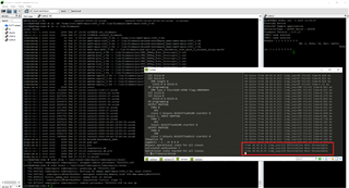
手动启动 R5F、ESC 正在运行、但 CPSW 已停止、
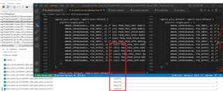
这是我的 syscfg、
/**
 * These arguments were used when this file was generated. They will be automatically applied on subsequent loads
 * via the GUI or CLI. Run CLI with '--help' for additional information on how to override these arguments.
 * @cliArgs --device "AM64x_beta" --package "ALV" --part "Default" --context "r5fss0-0" --product "MCU_PLUS_SDK_AM64x@08.06.00"
 * @versions {"tool":"1.14.0+2667"}
 */

/**
 * Import the modules used in this configuration.
 */
const eeprom     = scripting.addModule("/board/eeprom/eeprom", {}, false);
const eeprom1    = eeprom.addInstance();
const flash      = scripting.addModule("/board/flash/flash", {}, false);
const flash1     = flash.addInstance();
const led        = scripting.addModule("/board/led/led", {}, false);
const led1       = led.addInstance();
const led2       = led.addInstance();
const led3       = led.addInstance();
const gpio       = scripting.addModule("/drivers/gpio/gpio", {}, false);
const gpio1      = gpio.addInstance();
const gpio2      = gpio.addInstance();
const i2c        = scripting.addModule("/drivers/i2c/i2c", {}, false);
const i2c1       = i2c.addInstance();
const ipc        = scripting.addModule("/drivers/ipc/ipc");
const ethercat   = scripting.addModule("/industrial_comms/ethercat/ethercat", {}, false);
const ethercat1  = ethercat.addInstance();
const debug_log  = scripting.addModule("/kernel/dpl/debug_log");
const mpu_armv7  = scripting.addModule("/kernel/dpl/mpu_armv7", {}, false);
const mpu_armv71 = mpu_armv7.addInstance();
const mpu_armv72 = mpu_armv7.addInstance();
const mpu_armv73 = mpu_armv7.addInstance();
const mpu_armv74 = mpu_armv7.addInstance();
const mpu_armv75 = mpu_armv7.addInstance();
const mpu_armv76 = mpu_armv7.addInstance();
const mpu_armv77 = mpu_armv7.addInstance();

/**
 * Write custom configuration values to the imported modules.
 */
eeprom1.$name = "CONFIG_EEPROM0";

flash1.$name                  = "CONFIG_FLASH0";
flash1.peripheralDriver.$name = "CONFIG_OSPI0";

led1.$name = "CONFIG_LED_DIGITAL_OUTPUT";
led1.name  = "TPIC2810";

led2.$name = "CONFIG_LED_RUN";

led3.$name   = "CONFIG_LED_ERROR";
led3.ioIndex = 16;

gpio1.$name                    = "CONFIG_GPIO0";
led2.peripheralDriver          = gpio1;
gpio1.pinDir                   = "OUTPUT";
gpio1.useMcuDomainPeripherals  = true;
gpio1.MCU_GPIO.gpioPin.$assign = "ball.A7";

gpio2.$name                    = "CONFIG_GPIO1";
led3.peripheralDriver          = gpio2;
gpio2.useMcuDomainPeripherals  = true;
gpio2.MCU_GPIO.gpioPin.$assign = "ball.C7";

eeprom1.peripheralDriver = i2c1;
led1.peripheralDriver    = i2c1;
i2c1.$name               = "CONFIG_I2C0";
i2c1.I2C.$assign         = "I2C0";

ipc.enableLinuxIpc = true;

ethercat1.$name              = "CONFIG_ETHERCAT0";
ethercat1.instance           = "ICSSG1";
ethercat1.ethphy[0].$name    = "CONFIG_ETHPHY0";
ethercat1.ethphy[1].$name    = "CONFIG_ETHPHY1";
ethercat1.ethphy[1].mdioPort = 3;

const pruicss                            = scripting.addModule("/drivers/pruicss/pruicss", {}, false);
const pruicss1                           = pruicss.addInstance({}, false);
pruicss1.$name                           = "CONFIG_PRU_ICSS1";
ethercat1.icss                           = pruicss1;
pruicss1.AdditionalICSSSettings[0].$name = "CONFIG_PRU_ICSS_IO0";

debug_log.enableCssLog                    = false;
debug_log.enableUartLog                   = true;
debug_log.enableLogZoneInfo               = true;
debug_log.uartLog.$name                   = "CONFIG_UART0";
debug_log.uartLog.useMcuDomainPeripherals = true;
debug_log.uartLog.MCU_UART.$assign        = "MCU_USART0";

mpu_armv71.$name             = "CONFIG_MPU_REGION0";
mpu_armv71.size              = 31;
mpu_armv71.attributes        = "Device";
mpu_armv71.accessPermissions = "Supervisor RD+WR, User RD";
mpu_armv71.allowExecute      = false;

mpu_armv72.$name             = "CONFIG_MPU_REGION1";
mpu_armv72.size              = 15;
mpu_armv72.accessPermissions = "Supervisor RD+WR, User RD";

mpu_armv73.$name             = "CONFIG_MPU_REGION2";
mpu_armv73.baseAddr          = 0x41010000;
mpu_armv73.size              = 15;
mpu_armv73.accessPermissions = "Supervisor RD+WR, User RD";

mpu_armv74.$name             = "CONFIG_MPU_REGION3";
mpu_armv74.baseAddr          = 0x70000000;
mpu_armv74.size              = 21;
mpu_armv74.accessPermissions = "Supervisor RD+WR, User RD";

mpu_armv75.$name        = "CONFIG_MPU_REGION4";
mpu_armv75.attributes   = "NonCached";
mpu_armv75.allowExecute = false;
mpu_armv75.size         = 16;
mpu_armv75.baseAddr     = 0xA5000000;

mpu_armv76.$name    = "CONFIG_MPU_REGION5";
mpu_armv76.baseAddr = 0x80000000;
mpu_armv76.size     = 31;

mpu_armv77.$name        = "CONFIG_MPU_REGION6";
mpu_armv77.size         = 20;
mpu_armv77.baseAddr     = 0xA0000000;
mpu_armv77.attributes   = "NonCached";
mpu_armv77.allowExecute = false;

/**
 * Pinmux solution for unlocked pins/peripherals. This ensures that minor changes to the automatic solver in a future
 * version of the tool will not impact the pinmux you originally saw.  These lines can be completely deleted in order to
 * re-solve from scratch.
 */
flash1.peripheralDriver.OSPI.$suggestSolution                = "OSPI0";
flash1.peripheralDriver.OSPI.CLK.$suggestSolution            = "ball.N20";
flash1.peripheralDriver.OSPI.CSn0.$suggestSolution           = "ball.L19";
flash1.peripheralDriver.OSPI.DQS.$suggestSolution            = "ball.N19";
flash1.peripheralDriver.OSPI.D7.$suggestSolution             = "ball.M17";
flash1.peripheralDriver.OSPI.D6.$suggestSolution             = "ball.N18";
flash1.peripheralDriver.OSPI.D5.$suggestSolution             = "ball.P20";
flash1.peripheralDriver.OSPI.D4.$suggestSolution             = "ball.P21";
flash1.peripheralDriver.OSPI.D3.$suggestSolution             = "ball.M21";
flash1.peripheralDriver.OSPI.D2.$suggestSolution             = "ball.M20";
flash1.peripheralDriver.OSPI.D1.$suggestSolution             = "ball.M18";
flash1.peripheralDriver.OSPI.D0.$suggestSolution             = "ball.M19";
gpio1.MCU_GPIO.$suggestSolution                              = "MCU_GPIO0";
gpio2.MCU_GPIO.$suggestSolution                              = "MCU_GPIO0";
i2c1.I2C.SCL.$suggestSolution                                = "ball.A18";
i2c1.I2C.SDA.$suggestSolution                                = "ball.B18";
ethercat1.PRU_ICSSG1_MDIO.$suggestSolution                   = "PRU_ICSSG1_MDIO0";
ethercat1.PRU_ICSSG1_MDIO.MDC.$suggestSolution               = "ball.Y6";
ethercat1.PRU_ICSSG1_MDIO.MDIO.$suggestSolution              = "ball.AA6";
ethercat1.PRU_ICSSG1_IEP.$suggestSolution                    = "PRU_ICSSG1_IEP0";
ethercat1.PRU_ICSSG1_IEP.EDC_LATCH_IN0.$suggestSolution      = "ball.V7";
ethercat1.PRU_ICSSG1_IEP.EDC_LATCH_IN1.$suggestSolution      = "ball.U13";
ethercat1.PRU_ICSSG1_IEP.EDC_SYNC_OUT0.$suggestSolution      = "ball.W7";
ethercat1.PRU_ICSSG1_IEP.EDC_SYNC_OUT1.$suggestSolution      = "ball.U7";
ethercat1.PRU_ICSSG1_IEP.EDIO_DATA_IN_OUT28.$suggestSolution = "ball.U15";
ethercat1.PRU_ICSSG1_IEP.EDIO_DATA_IN_OUT29.$suggestSolution = "ball.U14";
ethercat1.PRU_ICSSG1_IEP.EDIO_DATA_IN_OUT30.$suggestSolution = "ball.V14";
ethercat1.PRU_ICSSG1_IEP.EDIO_DATA_IN_OUT31.$suggestSolution = "ball.W14";
ethercat1.PRU_ICSSG1_MII_G_RT.$suggestSolution               = "PRU_ICSSG1_MII_G_RT";
ethercat1.PRU_ICSSG1_MII_G_RT.MII0_RXD0.$suggestSolution     = "ball.Y7";
ethercat1.PRU_ICSSG1_MII_G_RT.MII0_RXD1.$suggestSolution     = "ball.U8";
ethercat1.PRU_ICSSG1_MII_G_RT.MII0_RXD2.$suggestSolution     = "ball.W8";
ethercat1.PRU_ICSSG1_MII_G_RT.MII0_RXD3.$suggestSolution     = "ball.V8";
ethercat1.PRU_ICSSG1_MII_G_RT.MII0_RXDV.$suggestSolution     = "ball.Y8";
ethercat1.PRU_ICSSG1_MII_G_RT.MII0_RXER.$suggestSolution     = "ball.V13";
ethercat1.PRU_ICSSG1_MII_G_RT.MII0_RXLINK.$suggestSolution   = "ball.W13";
ethercat1.PRU_ICSSG1_MII_G_RT.MII0_TXD0.$suggestSolution     = "ball.AA8";
ethercat1.PRU_ICSSG1_MII_G_RT.MII0_TXD1.$suggestSolution     = "ball.U9";
ethercat1.PRU_ICSSG1_MII_G_RT.MII0_TXD2.$suggestSolution     = "ball.W9";
ethercat1.PRU_ICSSG1_MII_G_RT.MII0_TXD3.$suggestSolution     = "ball.AA9";
ethercat1.PRU_ICSSG1_MII_G_RT.MII0_TXEN.$suggestSolution     = "ball.Y9";
ethercat1.PRU_ICSSG1_MII_G_RT.MII1_RXD0.$suggestSolution     = "ball.W11";
ethercat1.PRU_ICSSG1_MII_G_RT.MII1_RXD1.$suggestSolution     = "ball.V11";
ethercat1.PRU_ICSSG1_MII_G_RT.MII1_RXD2.$suggestSolution     = "ball.AA12";
ethercat1.PRU_ICSSG1_MII_G_RT.MII1_RXD3.$suggestSolution     = "ball.Y12";
ethercat1.PRU_ICSSG1_MII_G_RT.MII1_RXDV.$suggestSolution     = "ball.W12";
ethercat1.PRU_ICSSG1_MII_G_RT.MII1_RXER.$suggestSolution     = "ball.AA13";
ethercat1.PRU_ICSSG1_MII_G_RT.MII1_RXLINK.$suggestSolution   = "ball.U12";
ethercat1.PRU_ICSSG1_MII_G_RT.MII1_TXD0.$suggestSolution     = "ball.AA10";
ethercat1.PRU_ICSSG1_MII_G_RT.MII1_TXD1.$suggestSolution     = "ball.V10";
ethercat1.PRU_ICSSG1_MII_G_RT.MII1_TXD2.$suggestSolution     = "ball.U10";
ethercat1.PRU_ICSSG1_MII_G_RT.MII1_TXD3.$suggestSolution     = "ball.AA11";
ethercat1.PRU_ICSSG1_MII_G_RT.MII1_TXEN.$suggestSolution     = "ball.Y11";
ethercat1.PRU_ICSSG1_MII_G_RT.MII_MR0_CLK.$suggestSolution   = "ball.AA7";
ethercat1.PRU_ICSSG1_MII_G_RT.MII_MR1_CLK.$suggestSolution   = "ball.U11";
ethercat1.PRU_ICSSG1_MII_G_RT.MII_MT0_CLK.$suggestSolution   = "ball.V9";
ethercat1.PRU_ICSSG1_MII_G_RT.MII_MT1_CLK.$suggestSolution   = "ball.Y10";
debug_log.uartLog.MCU_UART.RXD.$suggestSolution              = "ball.A9";
debug_log.uartLog.MCU_UART.TXD.$suggestSolution              = "ball.A8";
请帮助解决该问题。