This thread has been locked.

If you have a related question, please click the "Ask a related question" button in the top right corner. The newly created question will be automatically linked to this question.

[参考译文] LAUNCHXL-CC1310:15.4 LRM 在加入网络后无响应

Guru**** 2540720 points
Other Parts Discussed in Thread: SYSCONFIG, CC1310

请注意,本文内容源自机器翻译,可能存在语法或其它翻译错误,仅供参考。如需获取准确内容,请参阅链接中的英语原文或自行翻译。

https://e2e.ti.com/support/wireless-connectivity/sub-1-ghz-group/sub-1-ghz/f/sub-1-ghz-forum/1038042/launchxl-cc1310-15-4-lrm-not-responding-after-joining-network

器件型号:LAUNCHXL-CC1310
Thread 中讨论的其他器件:SysConfigCC1310

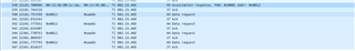
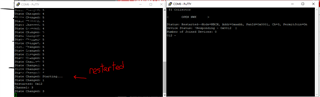
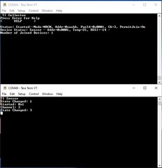
目前使用 CC1352作为收集器、使用 CC1310作为传感器、但当我尝试测试 LRM 时、在传感器连接后它不响应(标准50kbps PHY 工作正常)。  我正在使用库存15.4收集器和传感器示例、仅更改 SysConfig (CC1352)中的设置和 config.h (CC1310)中的#define CONFIG_PHY_ID (APIMAC_general_US_LRM_915_PHY_129)。  我已将数据包监听器与 Wireshark 连接、似乎在收集器关联响应之后、传感器请求数据和收集器 ACK、但数据未提供。 是否还有其他需要更改的设置才能正常工作。


  • 请注意,本文内容源自机器翻译,可能存在语法或其它翻译错误,仅供参考。如需获取准确内容,请参阅链接中的英语原文或自行翻译。

    您好、Corey、

    在我能为您提供帮助之前、我需要先向您提出一些问题。

    1.两个项目都使用哪种 SDK?

    2.您使用哪种工作模式? 信标、非信标、跳频?

    3.您提到传感器连接、但它没有响应。 这是否意味着传感器和收集器都指示关联在各自的 CUIS 中成功?

    4.您能否为传感器和收集器提供配置文件的一些代码片段(例如、对于 CC1310为 config.h、对于 CC1352为 ti_154stack_config.h)? 这将使我们能够看到配置的任何问题。

    谢谢。

    BR、
    安德烈斯

  • 请注意,本文内容源自机器翻译,可能存在语法或其它翻译错误,仅供参考。如需获取准确内容,请参阅链接中的英语原文或自行翻译。

    安德烈斯  

    感谢您的帮助。  

    1.1352 (收集器):SDK 5.20.00.52、 1310  (传感器):SDK 4.10.1.01

    2.非信标模式

    3.是的,在两个 CUI 上,它们都显示关联成功,然后在收集器 CUI 上显示!Responding

    1310 config.h

    ******************************************************************************
     Constants and definitions
     *****************************************************************************/
    /* config parameters */
    /*! Security Enable - set to true to turn on security */
    #define CONFIG_SECURE                true
    /*! PAN ID */
    #define CONFIG_PAN_ID                0xFFFF
    /*! FH disabled as default */
    #define CONFIG_FH_ENABLE             false
    /*! link quality */
    #define CONFIG_LINKQUALITY           1
    /*! percent filter */
    #define CONFIG_PERCENTFILTER         0xFF
    
    /*!
     Beacon order, value of 15 indicates non beacon mode,
     8 is a good value for beacon mode
    */
    #define CONFIG_MAC_BEACON_ORDER          15
    /*!
     Superframe order, value of 15 indicates non beacon mode,
     8 is a good value for beacon mode
    */
    #define CONFIG_MAC_SUPERFRAME_ORDER      15
    /*! Maximum number of message failure, to indicate sync loss */
    #define CONFIG_MAX_DATA_FAILURES     3
    /*!
     Maximum number of attempts for association in FH mode
     after reception of a PAN Config frame
     */
    #define CONFIG_FH_MAX_ASSOCIATION_ATTEMPTS    3
    /* Interval for scan backoff */
    #define CONFIG_SCAN_BACKOFF_INTERVAL  5000
    /* Interval for delay between orphan notifications */
    #define CONFIG_ORPHAN_BACKOFF_INTERVAL 300000
    
    /*! Setting for Phy ID */
    //#define CONFIG_PHY_ID                (APIMAC_STD_US_915_PHY_1)
    #define CONFIG_PHY_ID                (APIMAC_GENERIC_US_LRM_915_PHY_129)
    
    
    /*! MAC Parameter */
    /*! Min BE - Minimum Backoff Exponent */
    #define CONFIG_MIN_BE   3
    /*! Max BE - Maximum Backoff Exponent */
    #define CONFIG_MAX_BE   5
    /*! MAC MAX CSMA Backoffs */
    #define CONFIG_MAC_MAX_CSMA_BACKOFFS   4
    /*! macMaxFrameRetries - Maximum Frame Retries */
    #define CONFIG_MAX_RETRIES   3
    
    #if ((CONFIG_PHY_ID >= APIMAC_MRFSK_STD_PHY_ID_BEGIN) && (CONFIG_PHY_ID <= APIMAC_MRFSK_STD_PHY_ID_END))
    /*! Setting for channel page */
    #define CONFIG_CHANNEL_PAGE          (APIMAC_CHANNEL_PAGE_9)
    #elif ((CONFIG_PHY_ID >= APIMAC_MRFSK_GENERIC_PHY_ID_BEGIN) && (CONFIG_PHY_ID <= APIMAC_MRFSK_GENERIC_PHY_ID_END))
    /*! Setting for channel page */
    #define CONFIG_CHANNEL_PAGE          (APIMAC_CHANNEL_PAGE_10)
    #else
    #error "PHY ID is wrong."
    #endif
    
    #if (defined(CC1312R1_LAUNCHXL))
    #if((CONFIG_PHY_ID == APIMAC_GENERIC_CHINA_433_PHY_128) || (CONFIG_PHY_ID == APIMAC_GENERIC_CHINA_LRM_433_PHY_130))
    #error "Error: 433 MHz Operation is not supported on 1312 board!"
    #endif
    #endif
    
    /*! scan duration in seconds*/
    #define CONFIG_SCAN_DURATION         5
    
    /*!
     Coordinator Short Address When Operating with FH Enabled.
     */
    #define FH_COORD_SHORT_ADDR 0xAABB
    /*!
     Range Extender Mode setting.
     The following modes are available.
     APIMAC_NO_EXTENDER - does not have PA/LNA
     APIMAC_HIGH_GAIN_MODE - high gain mode
     To enable CC1190, use
     #define CONFIG_RANGE_EXT_MODE       APIMAC_HIGH_GAIN_MODE
    */
    #define CONFIG_RANGE_EXT_MODE       APIMAC_NO_EXTENDER
    
    /*! Setting Default Key*/
    #define KEY_TABLE_DEFAULT_KEY {0x12, 0x34, 0x56, 0x78, 0x9a, 0xbc, 0xde, 0xf0,\
                                   0x00, 0x00, 0x00, 0x00, 0x00, 0x00, 0x00, 0x00}
    
    /*!
     Channel mask used when CONFIG_FH_ENABLE is false.
     Each bit indicates if the corresponding channel is to be scanned
     First byte represents channels 0 to 7 and the last byte represents
     channels 128 to 135.
     For byte zero in the bit mask, LSB representing Ch0.
     For byte 1, LSB represents Ch8 and so on.
     e.g., 0x01 0x10 represents Ch0 and Ch12 are included.
     The default of 0x0F represents channels 0-3 are selected.
     APIMAC_STD_US_915_PHY_1 (50kbps/2-FSK/915MHz band) has channels 0 - 128.
     APIMAC_STD_ETSI_863_PHY_3 (50kbps/2-FSK/863MHz band) has channels 0 - 33.
     APIMAC_GENERIC_CHINA_433_PHY_128 (50kbps/2-FSK/433MHz band) has channels 0 - 6.
    */
    #define CONFIG_CHANNEL_MASK           { 0x0F, 0x00, 0x00, 0x00, 0x00, 0x00, \
                                            0x00, 0x00, 0x00, 0x00, 0x00, 0x00, \
                                            0x00, 0x00, 0x00, 0x00, 0x00 }
    /*!
     Channel mask used when CONFIG_FH_ENABLE is true.
     Represents the list of channels on which the device can hop.
     When CONFIG_RX_ON_IDLE is true, the actual sequence will
     be based on DH1CF function. When it is set to false, the sequence
     shall be a linear hopping over available channels in ascending order and
     shall be used to change channel during the join phase.
     It is represented as a bit string with LSB representing Ch0.
     e.g., 0x01 0x10 represents Ch0 and Ch12 are included.
     */
    #define CONFIG_FH_CHANNEL_MASK        { 0xFF, 0xFF, 0xFF, 0xFF, 0xFF, 0xFF, \
                                            0xFF, 0x00, 0x00, 0x00, 0x00, 0x00, \
                                            0x00, 0x00, 0x00, 0x00, 0x00,}
    /* FH related config variables */
    /*!
     List of channels to target the Async frames
     It is represented as a bit string with LSB representing Ch0
     e.g., 0x01 0x10 represents Ch0 and Ch12 are included
     It should cover all channels that could be used by a target device in its
     hopping sequence. Channels marked beyond number of channels supported by
     PHY Config will be excluded by stack. To avoid interference on a channel,
     it should be removed from Async Mask and added to exclude channels
     (CONFIG_CHANNEL_MASK).
     */
    #define FH_ASYNC_CHANNEL_MASK         { 0xFF, 0xFF, 0xFF, 0xFF, 0xFF, 0xFF, \
                                            0xFF, 0xFF, 0xFF, 0xFF, 0xFF, 0xFF, \
                                            0xFF, 0xFF, 0xFF, 0xFF, 0xFF }
    
    /*! Rx on when idle, false for sleepy device, true for non sleepy device */
    #define CONFIG_RX_ON_IDLE          false
    
    /*!
     The number of non sleepy channel hopping end devices to be supported.
     It is to be noted that the total number of non sleepy devices supported
      must be less than 50. Stack will allocate memory proportional
     to the number of end devices requested.
     */
    #define FH_NUM_NON_SLEEPY_HOPPING_NEIGHBORS  2
    /*!
     The number of non sleepy fixed channel end devices to be supported.
     It is to be noted that the total number of non sleepy devices supported
      must be less than 50. Stack will allocate memory proportional
     to the number of end devices requested.
     */
    #define FH_NUM_NON_SLEEPY_FIXED_CHANNEL_NEIGHBORS  2
    
    /*!
     Dwell Time: The duration for which a non sleepy end device shall
     stay on a specific channel before hopping to next channel.
     */
    #define CONFIG_DWELL_TIME            250
    
    #if (((CONFIG_PHY_ID >= APIMAC_MRFSK_STD_PHY_ID_BEGIN) && (CONFIG_PHY_ID <= APIMAC_MRFSK_GENERIC_PHY_ID_BEGIN)) || \
        ((CONFIG_PHY_ID >= APIMAC_GENERIC_US_915_PHY_132) && (CONFIG_PHY_ID <= APIMAC_GENERIC_ETSI_863_PHY_133)))
    /*! Default Polling interval in milliseconds. It will get updated upon reception
     of a config request message */
    #define CONFIG_POLLING_INTERVAL      6000
    /*! PAN Advertisement Solicit trickle timer duration in milliseconds */
    #define CONFIG_PAN_ADVERT_SOLICIT_CLK_DURATION    6000
    /*! PAN Config Solicit trickle timer duration in milliseconds */
    #define CONFIG_PAN_CONFIG_SOLICIT_CLK_DURATION    6000
    /*! Default Reporting Interval - in milliseconds. It will get updated upon
     reception of a config request message */
    #define CONFIG_REPORTING_INTERVAL  180000
    #else
    /*! Default Polling interval in milliseconds. It will get updated upon reception
     of a config request message */
    #define CONFIG_POLLING_INTERVAL      60000
    /*! PAN Advertisement Solicit trickle timer duration in milliseconds */
    #define CONFIG_PAN_ADVERT_SOLICIT_CLK_DURATION    60000
    /*! PAN Config Solicit trickle timer duration in milliseconds */
    #define CONFIG_PAN_CONFIG_SOLICIT_CLK_DURATION    60000
    /*! Default Reporting Interval - in milliseconds. It will get updated upon
     reception of a config request message */
    #define CONFIG_REPORTING_INTERVAL  600000
    #endif
    
    /*! FH Poll/Sensor msg start time randomization window */
    #define CONFIG_FH_START_POLL_DATA_RAND_WINDOW   10000
    
    /*! If enabled, the periodic sensor message shall be sent as a fixed size
     * packet of specified size. If set to 0, the periodic sensor message shall be
     * of type sensor data specified in smsgs.h
     */
    #define SENSOR_TEST_RAMP_DATA_SIZE   0
    
    /*! value for ApiMac_FHAttribute_netName */
    #define CONFIG_FH_NETNAME            {"FHTest"}
    
    /*! Range Extender is not supported in uBLE project  */
    #ifdef FEATURE_UBLE
    #if CONFIG_RANGE_EXT_MODE
    #error "CONFIG_RANGE_EXT_MODE should be APIMAC_NO_EXTENDER"
    #endif
    #endif
    
    /*!
     Value for Transmit Power in dBm
     For US and ETSI band, Default value is 10, allowed values are
     -10, 0, 1, 2, 3, 4, 5, 6, 7, 8, 9, 10, 11, 12 and 14dBm.
     For China band, allowed values are 6, 10, 13, 14 and 15dBm.
     For CC1190, allowed values are between 18, 23, 25, 26 and 27dBm.
     When the nodes in the network are close to each other
     lowering this value will help reduce saturation */
    #ifndef DeviceFamily_CC13X2
    #if CONFIG_RANGE_EXT_MODE
    #define CONFIG_TRANSMIT_POWER        26
    #else
    #if ((CONFIG_PHY_ID == APIMAC_GENERIC_CHINA_433_PHY_128) || (CONFIG_PHY_ID == APIMAC_GENERIC_CHINA_LRM_433_PHY_130))
    #define CONFIG_TRANSMIT_POWER        14
    #else
    #define CONFIG_TRANSMIT_POWER        12
    #endif
    #endif
    #else /* DeviceFamily_CC13X2 */
    #define CONFIG_TRANSMIT_POWER        12
    #endif
    
    #ifndef DeviceFamily_CC13X2
    #if CONFIG_RANGE_EXT_MODE
    #if (CCFG_FORCE_VDDR_HH == 1)
    #error "CCFG_FORCE_VDDR_HH should be 0"
    #endif
    #else
    #if ((CONFIG_PHY_ID == APIMAC_GENERIC_CHINA_433_PHY_128) || (CONFIG_PHY_ID == APIMAC_GENERIC_CHINA_LRM_433_PHY_130))
    #if (CCFG_FORCE_VDDR_HH == 0)
    #if (CONFIG_TRANSMIT_POWER >= 15)
    #error "CONFIG_TRANSMIT_POWER should be less than 15"
    #endif
    #else
    #if (CONFIG_TRANSMIT_POWER < 15)
    /* In 433 MHz band when CCFG_FORCE_VDDR_HH = 1, only possible value of transmit power is 15 */
    #error "CONFIG_TRANSMIT_POWER should be 15"
    #endif
    #endif
    #else
    #if (CCFG_FORCE_VDDR_HH == 0)
    #if (CONFIG_TRANSMIT_POWER >= 14)
    #error "CONFIG_TRANSMIT_POWER should be less than 14"
    #endif
    #else
    #if (CONFIG_TRANSMIT_POWER < 14)
    /* In US and ETSI band when CCFG_FORCE_VDDR_HH = 1, only possible value of transmit power is 14 */
    #error "CONFIG_TRANSMIT_POWER should be 14"
    #endif
    #endif
    #endif
    #endif
    #else
    #if (CCFG_FORCE_VDDR_HH == 1)
    #if (CONFIG_TRANSMIT_POWER != 14)
    /* In US and ETSI band when CCFG_FORCE_VDDR_HH = 1, only possible value of transmit power is 14 */
    #error "CONFIG_TRANSMIT_POWER should be 14"
    #endif
    #endif
    #endif
    
    /*!
    * Enable this mode for certfication.
    * For FH certification, CONFIG_FH_ENABLE should
    * also be enabled
    */
    #define CERTIFICATION_TEST_MODE     false
    
    #ifdef POWER_MEAS
    /*!
     Power profile to be used when Power MEAS is enabled.
     Profile 1 - POLL_ACK - Polling Only
     Profile 2 - DATA_ACK - 20 byte application data + ACK from sensor to collector
     Profile 3 - POLL_DATA - Poll + received Data from collector
     Profile 4 - SLEEP - No Poll or Data. In Beacon mode, beacon RX would occur
     */
    #define POWER_TEST_PROFILE  DATA_ACK
    #endif
    
    /* Check if all the necessary parameters have been set for FH mode */
    #if CONFIG_FH_ENABLE
    #if !defined(FEATURE_ALL_MODES) && !defined(FEATURE_FREQ_HOP_MODE)
    #error "Do you want to build image with frequency hopping mode? \
            Define either FEATURE_FREQ_HOP_MODE or FEATURE_ALL_MODES in features.h"
    #endif
    #endif
    
    /* Check if stack level security is enabled if application security is enabled */
    #if CONFIG_SECURE
    #if !defined(FEATURE_MAC_SECURITY)
    #error "Define FEATURE_MAC_SECURITY or FEATURE_ALL_MODES in features.h to \
            be able to use security at application level"
    #endif
    #endif
    
    /* Set beacon order and superframe order to 15 for FH mode to avoid user error */
    #if CONFIG_FH_ENABLE
    #if (CONFIG_MAC_BEACON_ORDER != 15) && (CONFIG_MAC_SUPERFRAME_ORDER != 15)
    #error "Do you want to build image with frequency hopping mode? \
        If yes, CONFIG_MAC_BEACON_ORDER and CONFIG_MAC_SUPERFRAME_ORDER \
        should both be set to 15"
    #endif
    #if (FH_NUM_NON_SLEEPY_HOPPING_NEIGHBORS < 2) || (FH_NUM_NON_SLEEPY_FIXED_CHANNEL_NEIGHBORS < 2)
    #error "You have an invalid value for FH neighbors. Set the values \
            for FH_NUM_NON_SLEEPY_HOPPING_NEIGHBORS and FH_NUM_NON_SLEEPY_FIXED_CHANNEL_NEIGHBORS to at least 2"
    #endif
    #endif
    
    #ifdef __cplusplus
    }
    #endif
    
    #endif /* CONFIG_H */


    对于1352、我不知道  ti_154stack_config.h 文件( 未看到该文件、我看到 mac_setting.h、mac_user_config.h、macconfig.h、 ti_154stack_overrides.h)。 我要做的只是更改收集器 SysConfig 文件中的收集器 PHY 类型

  • 请注意,本文内容源自机器翻译,可能存在语法或其它翻译错误,仅供参考。如需获取准确内容,请参阅链接中的英语原文或自行翻译。

    您好、Corey、

    ti_154stack_config.h 文件是 SysConfig 生成的文件之一。 因此、这不是一个应编辑的文件(在使用 SysConfig 设置更改后)、但您只需检查一下传感器配置和收集器配置之间是否存在任何不一致之处即可。

    您只需构建项目、然后在项目资源管理器中打开项目、然后单击:Generated Source -> SysConfig -> ti_154stack_config.h

    请与我共享该文件、我们可以从那里转到。

    BR、
    安德烈斯

  • 请注意,本文内容源自机器翻译,可能存在语法或其它翻译错误,仅供参考。如需获取准确内容,请参阅链接中的英语原文或自行翻译。

    ti_154stack_config.h   

    /******************************************************************************
     DO NOT EDIT - This file is generated by the SysConfig tool.
     @file ti_154stack_config.h
    
     @brief TI-15.4 Stack configuration parameters for Collector
     applications
    
     *****************************************************************************/
    #ifndef TI_154STACK_CONFIG_H
    #define TI_154STACK_CONFIG_H
    
    /******************************************************************************
     Includes
     *****************************************************************************/
    #include "api_mac.h"
    #include "ti_154stack_features.h"
    
    #ifdef __cplusplus
    extern "C"
    {
    #endif
    
    /* Setting for PAN ID */
    #define CONFIG_PAN_ID                   0xFFFF
    
    /* Setting for phy ID */
    #define CONFIG_PHY_ID                   APIMAC_5KBPS_915MHZ_PHY_129
    
    /* Setting for channel page */
    #define CONFIG_CHANNEL_PAGE             APIMAC_CHANNEL_PAGE_10
    
    /*
     Channel mask used when CONFIG_FH_ENABLE is false.
     Each bit indicates if the corresponding channel is to be scanned
     First byte represents channels 0 to 7 and the last byte represents
     channels 128 to 135.
     For byte zero in the bit mask, LSB representing Ch0.
     For byte 1, LSB represents Ch8 and so on.
     e.g., 0x01 0x10 represents Ch0 and Ch12 are included.
    */
    #define CONFIG_CHANNEL_MASK             { 0x0F,0x00,0x00,0x00,0x00,0x00, \
                                              0x00,0x00,0x00,0x00,0x00,0x00, \
                                              0x00,0x00,0x00,0x00,0x00 }
    
    /*
     Channel mask used when CONFIG_FH_ENABLE is true.
     Represents the list of channels on which the device can hop.
     The actual sequence used shall be based on DH1CF function.
     It is represented as a bit string with LSB representing Ch0.
     e.g., 0x01 0x10 represents Ch0 and Ch12 are included.
     */
     #define CONFIG_FH_CHANNEL_MASK         { 0xFF,0xFF,0xFF,0xFF,0xFF,0xFF, \
                                              0xFF,0xFF,0xFF,0xFF,0xFF,0xFF, \
                                              0xFF,0xFF,0xFF,0xFF,0x01 }
    
    /*
     List of channels to target asynchronous frames when CONFIG_FH_ENABLE = true.
     It is represented as a bit string with LSB representing Ch0
     e.g., 0x01 0x10 represents Ch0 and Ch12 are included
     It should cover all channels that could be used by a target device in its
     hopping sequence. Channels marked beyond number of channels supported by
     PHY Config will be excluded by stack. To avoid interference on a channel,
     it should be removed from Async Mask and excluded from the FH channel mask.
     */
    #define FH_ASYNC_CHANNEL_MASK           { 0xFF,0xFF,0xFF,0xFF,0xFF,0xFF, \
                                              0xFF,0xFF,0xFF,0xFF,0xFF,0xFF, \
                                              0xFF,0xFF,0xFF,0xFF,0x01 }
    
    /*
    Channel mask composed of all supported channels for selected PHY. Used to
    validate user input during runtime channel mask configuration.
    */
    #define CUI_VALID_CHANNEL_MASK          { 0xFF,0xFF,0xFF,0xFF,0xFF,0xFF, \
                                              0xFF,0xFF,0xFF,0xFF,0xFF,0xFF, \
                                              0xFF,0xFF,0xFF,0xFF,0x01 }
    
    /* Setting for FH network name attribute */
    #define CONFIG_FH_NETNAME               {"FHTest"}
    
    /* Setting for maximum devices in association table */
    #define CONFIG_MAX_DEVICES              50
    
    /*
     Setting for reporting interval - in milliseconds to be set on connected devices
     using configuration request messages
     */
    #define CONFIG_REPORTING_INTERVAL       3000
    
    /*
     Setting for polling interval - in milliseconds to be set on connected devices
     using configuration request messages
     */
    #define CONFIG_POLLING_INTERVAL         2000
    
    /* Setting for interval in ms between tracking message intervals */
    #define TRACKING_DELAY_TIME             5000
    
    /* Setting for scan duration in seconds */
    #define CONFIG_SCAN_DURATION            5
    
    /* Setting for beacon order */
    #define CONFIG_MAC_BEACON_ORDER         15
    
    /* Setting for superframe order */
    #define CONFIG_MAC_SUPERFRAME_ORDER     15
    
    /* Setting for minimum backoff exponent */
    #define CONFIG_MIN_BE                   3
    
    /* Setting for maximum backoff exponent */
    #define CONFIG_MAX_BE                   5
    
    /*
     Setting for FH application broadcast msg generation interval in ms. 
     The stack FH broadcast interval is half of this value to prevent
     transmit queue overflow.
     */
    #define FH_BROADCAST_INTERVAL           10000
    
    /* Setting for FH application broadcast dwell time in ms */
    #define FH_BROADCAST_DWELL_TIME         100
    
    /* ! Setting for transmit power in dBm */
    #define CONFIG_TRANSMIT_POWER           0
    
    /* Setting to enable frequency hopping mode */
    #define CONFIG_FH_ENABLE                false
    
    /* Setting to enable network security */
    #define CONFIG_SECURE                   true
    
    /* Setting for network security key*/
    #define KEY_TABLE_DEFAULT_KEY           { 0x12,0x34,0x56,0x78,0x9A,0xBC,0xDE,0xF0, \
                                              0x00,0x00,0x00,0x00,0x00,0x00,0x00,0x00 }
    
    /* Setting to enable certification test mode */
    #define CERTIFICATION_TEST_MODE         false
    
    #ifdef __cplusplus
    }
    #endif
    
    #endif /* TI_154STACK_CONFIG_H */
    

  • 请注意,本文内容源自机器翻译,可能存在语法或其它翻译错误,仅供参考。如需获取准确内容,请参阅链接中的英语原文或自行翻译。

    您好、Corey、

    感谢您提供该代码。 让我比较这两个配置文件并运行示例、看看我是否可以重现您看到的内容。

    完成此操作后、我将返回给您。

    BR、
    安德烈斯

  • 请注意,本文内容源自机器翻译,可能存在语法或其它翻译错误,仅供参考。如需获取准确内容,请参阅链接中的英语原文或自行翻译。

    您好!

    很抱歉耽误你的时间。 我检查了这两个文件、一切似乎都井然有序。 我确实注意到的一件奇怪的事情是 config.h 文件中的这些默认值非常高。

    #define CONFIG_POLLING_INTERVAL      60000
    #define CONFIG_REPORTING_INTERVAL  600000
    

    我认为这些值应该在关联发生时进行更新,但这可能不是它的工作方式(两个 SDK 中的示例之间可能存在一些差异)。 因此、我将其修改为更现实的内容:

    #define CONFIG_POLLING_INTERVAL      2000
    #define CONFIG_REPORTING_INTERVAL  3000

    现在、我看到:

    请尝试这些值并告诉我。

    BR、
    安德烈斯

  • 请注意,本文内容源自机器翻译,可能存在语法或其它翻译错误,仅供参考。如需获取准确内容,请参阅链接中的英语原文或自行翻译。

    这是修复、我最初看到了这些数字、我认为它们看起来有点大、但由于它们是 SDK 中的库存数字、我认为它们需要采用这种方法、但如果这导致了问题、可能应该在 SDK 中进行更改。 非常感谢您的帮助