请注意,本文内容源自机器翻译,可能存在语法或其它翻译错误,仅供参考。如需获取准确内容,请参阅链接中的英语原文或自行翻译。
器件型号:LAUNCHXL-CC1352P 主题中讨论的其他器件:CC2652P7、 CC1352P、SysConfig、 CC1352P7
海天
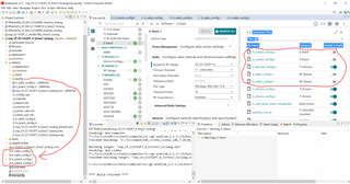
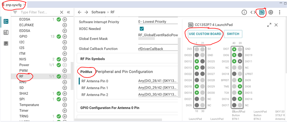
我尝试 为 Zigbee 网络处理器(ZNP)示例 CC2652P7 驱动器芯片。
我想使用20dBm 的输出功率。
我需要选择哪个 Launchpad?
如何设定目标?
需要执行任何其他配置?
此致
Bose
海天
我尝试 为 Zigbee 网络处理器(ZNP)示例 CC2652P7 驱动器芯片。
我想使用20dBm 的输出功率。
我需要选择哪个 Launchpad?
如何设定目标?
需要执行任何其他配置?
此致
Bose