使用Launchpad-28069+Drv8305,驱动一个外转子的电机(电感值在几个uH)。
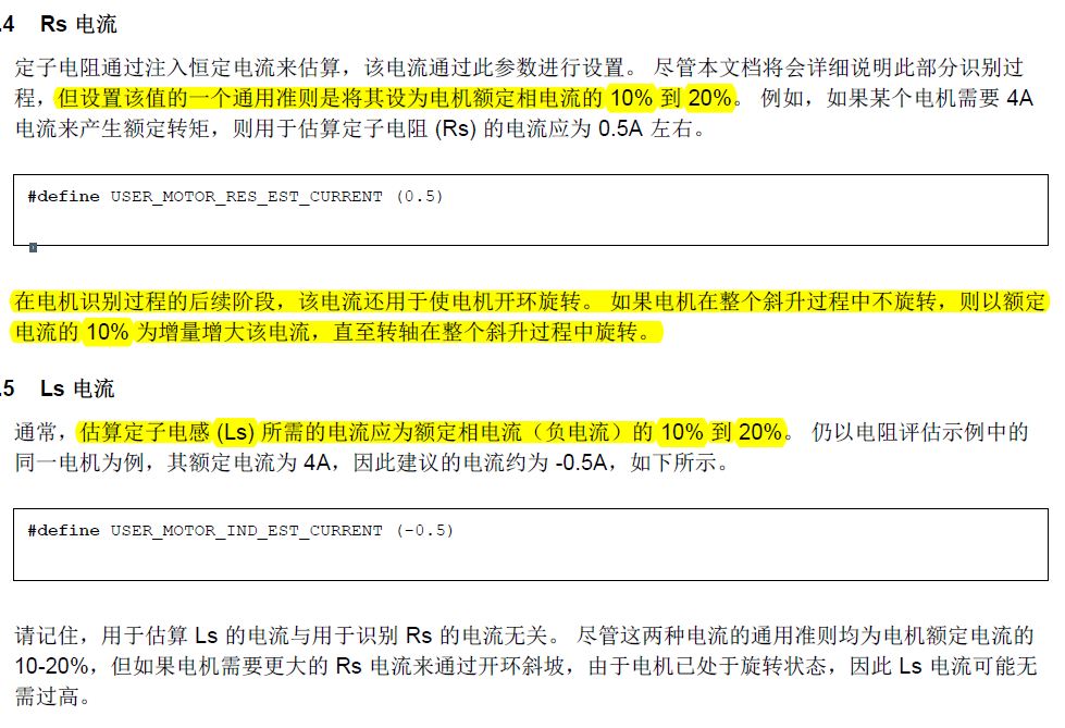
#define USER_MOTOR_RES_EST_CURRENT (2)
#define USER_MOTOR_IND_EST_CURRENT (-2)
按照上述配置时,电机可以正常完成参数辨识过程,辨识结果也比较准确。
但当我将上述参数改为3A时(user.h中的其他参数保持不变),电机无法完成正常的参数辨识,在进行到电感辨识的时候,发出很大的噪音,驱动板Drv8305报错。反复试过几次都是这样的问题,请问这是什么原因?
#define USER_MOTOR_RES_EST_CURRENT (3)
#define USER_MOTOR_IND_EST_CURRENT (-3)
手册中对这两个电流的解释为:只提到辨识电感时,电机也处于旋转状态,Ls电流可能无需过高。
1.一般都是把这两个值设置成相同的大小,符号相反。可不可以将RES = 3,IND = -1。是否可以?
2.由于进行参数辨识代码不开源,不知道他的辨识策略。是否有详细的文档可供参考?
但有注意到电机在进行电感辨识的过程中,有一个短暂的停止动作,这是什么情况?
希望得到TI工程师的回答,非常感谢!