


1、使用TMS320F28P650DK的TZ[OST]封锁PWM1和PWM2 时,如果开启CPUtimer0的中断,PWM1的封锁会失效。请假教TI专家,是什么原因导致?
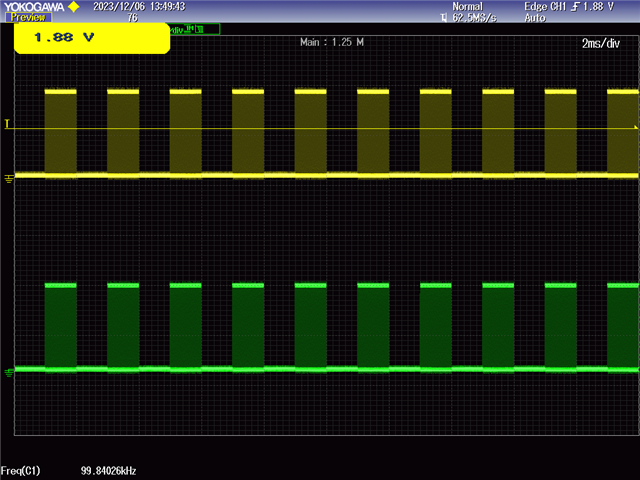
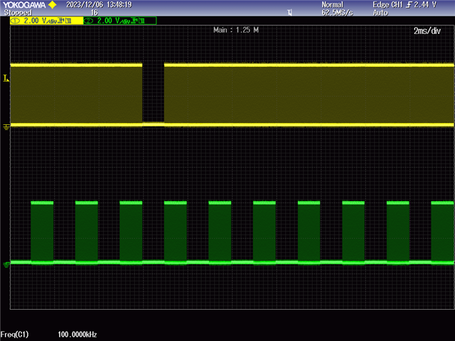
(1) 左图:关闭TIMER0_INT //PieCtrlRegs.PIEIER1.bit.INTx7 = 1; 右图:开启TIMER0_INT: PieCtrlRegs.PIEIER1.bit.INTx7 = 1;
(2)PWM1A——黄色 PWM2A——绿色
(3)TIMER0_INT 中断中无任何操作。
//###########################################################################
//
// FILE:   epwm_ex1_trip_zone.c
//
// TITLE:  ePWM module using Trip-Zone submodule.
//
//! \addtogroup cpu01_example_list
//! <h1> EPWM Trip Zone Module (epwm_trip_zone)</h1>
//!
//! This example configures ePWM1 and ePWM2 as follows
//!  - ePWM1 has TZ1 as one shot trip source
//!  - ePWM2 has TZ1 as cycle by cycle trip source
//!
//! Initially tie TZ1 high. During the test, monitor ePWM1 or ePWM2
//! outputs on a scope. Pull TZ1 low to see the effect.
//!
//!  \b External \b Connections \n
//!  - EPWM1A is on GPIO0
//!  - EPWM2A is on GPIO2
//!  - TZ1 is on GPIO12
//!
//! This example also makes use of the Input X-BAR. GPIO12 (the external
//! trigger) is routed to the input X_BAR, from which it is routed to TZ1.
//!
//! The TZ-Event is defined such that EPWM1A will undergo a One-Shot Trip
//! and EPWM2A will undergo a Cycle-By-Cycle Trip.
//!
//              _____________             __________________
//              |           |             |                |
//  GPIO12 -----| I/P X-BAR |-----TZ1-----| ePWM TZ Module |-----TZ-Event
//              |___________|             |________________|
//
//
//
//###########################################################################
//
//
// $Copyright:
// Copyright (C) 2022 Texas Instruments Incorporated - http://www.ti.com
//
// Redistribution and use in source and binary forms, with or without
// modification, are permitted provided that the following conditions
// are met:
//
//   Redistributions of source code must retain the above copyright
//   notice, this list of conditions and the following disclaimer.
//
//   Redistributions in binary form must reproduce the above copyright
//   notice, this list of conditions and the following disclaimer in the
//   documentation and/or other materials provided with the
//   distribution.
//
//   Neither the name of Texas Instruments Incorporated nor the names of
//   its contributors may be used to endorse or promote products derived
//   from this software without specific prior written permission.
//
// THIS SOFTWARE IS PROVIDED BY THE COPYRIGHT HOLDERS AND CONTRIBUTORS
// "AS IS" AND ANY EXPRESS OR IMPLIED WARRANTIES, INCLUDING, BUT NOT
// LIMITED TO, THE IMPLIED WARRANTIES OF MERCHANTABILITY AND FITNESS FOR
// A PARTICULAR PURPOSE ARE DISCLAIMED. IN NO EVENT SHALL THE COPYRIGHT
// OWNER OR CONTRIBUTORS BE LIABLE FOR ANY DIRECT, INDIRECT, INCIDENTAL,
// SPECIAL, EXEMPLARY, OR CONSEQUENTIAL DAMAGES (INCLUDING, BUT NOT
// LIMITED TO, PROCUREMENT OF SUBSTITUTE GOODS OR SERVICES; LOSS OF USE,
// DATA, OR PROFITS; OR BUSINESS INTERRUPTION) HOWEVER CAUSED AND ON ANY
// THEORY OF LIABILITY, WHETHER IN CONTRACT, STRICT LIABILITY, OR TORT
// (INCLUDING NEGLIGENCE OR OTHERWISE) ARISING IN ANY WAY OUT OF THE USE
// OF THIS SOFTWARE, EVEN IF ADVISED OF THE POSSIBILITY OF SUCH DAMAGE.
// $
//###########################################################################

//
// Included Files
//
#include "f28x_project.h"

//
// Defines
//
#define EXTTrig     // Leave Uncommented for Testing with External Trigger.
                    // Comment for Testing with ePWM Trigger.

//
// Globals
//
Uint32  EPwm1TZIntCount;
Uint32  EPwm2TZIntCount;

//
// Function Prototypes
//
void InitEPwm(void);

void InitEPwm_Gpio(void);


__interrupt void cpuTimer0ISR(void);
__interrupt void epwm_isr(void);
//
// Main
//

int cnt = 0;

void main(void)
{
//
// Step 1. Initialize System Control:
// PLL, WatchDog, enable Peripheral Clocks
// This example function is found in the f2838x_sysctrl.c file.
//
    InitSysCtrl();

//
// Step 2. Initialize GPIO:
// This example function is found in the f2838x_gpio.c file and
// illustrates how to set the GPIO to it's default state.
//
//    InitGpio();

//
// enable PWM1, and PWM2
//


//
// For this case just init GPIO pins for ePWM1, ePWM2, ePWM3
//
    InitEPwm_Gpio();

//
// Step 3. Clear all interrupts and initialize PIE vector table:
// Disable CPU interrupts
//
    DINT;

//
// Initialize the PIE control registers to their default state.
// The default state is all PIE interrupts disabled and flags
// are cleared.
// This function is found in the f2838x_piectrl.c file.
//
    InitPieCtrl();

//
// Disable CPU interrupts and clear all CPU interrupt flags:
//
    IER = 0x0000;
    IFR = 0x0000;

//
// Initialize the PIE vector table with pointers to the shell Interrupt
// Service Routines (ISR).
// This will populate the entire table, even if the interrupt
// is not used in this example.  This is useful for debug purposes.
// The shell ISR routines are found in f2838x_defaultisr.c.
// This function is found in f2838x_pievect.c.
//
    InitPieVectTable();

//
// Interrupts that are used in this example are re-mapped to
// ISR functions found within this file.
//
    EALLOW; // This is needed to write to EALLOW protected registers
    PieVectTable.TIMER0_INT = &cpuTimer0ISR;
    EDIS;   // This is needed to disable write to EALLOW protected registers

//
// Step 4. Initialize the Device Peripherals:
//
    EALLOW;
    CpuSysRegs.PCLKCR0.bit.TBCLKSYNC =0;
    EDIS;

   InitEPwm();

    EALLOW;
    CpuSysRegs.PCLKCR0.bit.TBCLKSYNC =1;
    EDIS;

    ConfigCpuTimer(&CpuTimer0, 200, 1000);
    CpuTimer0Regs.TCR.all = 0x4000;

//
// Step 5. User specific code, enable interrupts:
//

//
// Enable CPU INT3 which is connected to EPWM1-3 INT:
//
    IER |= M_INT1;

//
// Enable EPWM INTn in the PIE: Group 3 interrupt 1-3
//
    PieCtrlRegs.PIEIER1.bit.INTx7 = 1;

// Enable global Interrupts and higher priority real-time debug events:
//
    EINT;  // Enable Global interrupt INTM
    ERTM;  // Enable Global realtime interrupt DBGM

//
// Step 6. IDLE loop. Just sit and loop forever (optional):
//
    for(;;)
    {
        cnt++;
        if(cnt == 1)
        {
            EALLOW;
            EPwm1Regs.TZFRC.bit.OST = 0x01;
            EPwm2Regs.TZFRC.bit.OST = 0x01;
            EDIS;
        }
        else
        {
            cnt = 0;
            EALLOW;
            EPwm1Regs.TZCLR.bit.OST = 0x01;
            EPwm2Regs.TZCLR.bit.OST = 0x01;
            EDIS;
        }
        DELAY_US(1000);
    }
}


__interrupt void cpuTimer0ISR(void)
{

    PieCtrlRegs.PIEACK.all = PIEACK_GROUP1;
}

void InitEPwm()
{
    //
    // Enable TZ1 as one shot trip sources
    //
    EALLOW;
    EPwm1Regs.TZSEL.bit.OSHT1 = 1;

    //
    // Set TZA
    //
    EPwm1Regs.TZCTL.bit.TZA = TZ_FORCE_LO;
    EPwm1Regs.TZCTL.bit.TZB = TZ_FORCE_LO;
    //
    // Enable TZ interrupt
    //
    EPwm1Regs.TZEINT.bit.OST = 0;
    EDIS;

    EPwm1Regs.TBPRD = 1000;                        // Set timer period
    EPwm1Regs.TBPHS.bit.TBPHS = 0x0000;             // Phase is 0
    EPwm1Regs.TBCTR = 0x0000;                       // Clear counter

    //
    // Setup TBCLK
    //
    EPwm1Regs.TBCTL.bit.FREE_SOFT = 0x02;
    EPwm1Regs.TBCTL.bit.CTRMODE = TB_COUNT_UP; // Count up
    EPwm1Regs.TBCTL.bit.PHSEN = TB_DISABLE;        // Disable phase loading
    EPwm1Regs.TBCTL.bit.HSPCLKDIV = TB_DIV1;       // Clock ratio to SYSCLKOUT
    EPwm1Regs.TBCTL.bit.CLKDIV = TB_DIV1;

    EPwm1Regs.CMPCTL.bit.SHDWAMODE = CC_SHADOW;    // Load registers every ZERO
    EPwm1Regs.CMPCTL.bit.LOADAMODE = CC_CTR_ZERO;

    //
    // Setup compare
    //
    EPwm1Regs.CMPA.bit.CMPA = 500;
    EPwm1Regs.CMPB.bit.CMPB = 500;
    //
    // Set actions
    //
    EPwm1Regs.AQCTLA.bit.CAU = AQ_CLEAR;
    EPwm1Regs.AQCTLA.bit.ZRO = AQ_SET;
    EPwm1Regs.AQCTLB.bit.CAU = AQ_CLEAR;
    EPwm1Regs.AQCTLB.bit.ZRO = AQ_SET;

    //
       // Enable TZ1 as one shot trip sources
       //
       EALLOW;
       EPwm2Regs.TZSEL.bit.OSHT1 = 1;

       //
       // Set TZA
       //
       EPwm2Regs.TZCTL.bit.TZA = TZ_FORCE_LO;
       EPwm2Regs.TZCTL.bit.TZB = TZ_FORCE_LO;
       //
       // Enable TZ interrupt
       //
       EPwm2Regs.TZEINT.bit.OST = 0;
       EDIS;

       EPwm2Regs.TBPRD = 1000;                        // Set timer period
       EPwm2Regs.TBPHS.bit.TBPHS = 0x0000;             // Phase is 0
       EPwm2Regs.TBCTR = 0x0000;                       // Clear counter

       //
       // Setup TBCLK
       //
       EPwm2Regs.TBCTL.bit.FREE_SOFT = 0x02;
       EPwm2Regs.TBCTL.bit.CTRMODE = TB_COUNT_UP; // Count up
       EPwm2Regs.TBCTL.bit.PHSEN = TB_DISABLE;        // Disable phase loading
       EPwm2Regs.TBCTL.bit.HSPCLKDIV = TB_DIV1;       // Clock ratio to SYSCLKOUT
       EPwm2Regs.TBCTL.bit.CLKDIV = TB_DIV1;

       EPwm2Regs.CMPCTL.bit.SHDWAMODE = CC_SHADOW;    // Load registers every ZERO
       EPwm2Regs.CMPCTL.bit.LOADAMODE = CC_CTR_ZERO;

       //
       // Setup compare
       //
       EPwm2Regs.CMPA.bit.CMPA = 500;
       EPwm2Regs.CMPB.bit.CMPB = 500;
       //
       // Set actions
       //
       EPwm2Regs.AQCTLA.bit.CAU = AQ_CLEAR;
       EPwm2Regs.AQCTLA.bit.ZRO = AQ_SET;
       EPwm2Regs.AQCTLB.bit.CAU = AQ_CLEAR;
       EPwm2Regs.AQCTLB.bit.ZRO = AQ_SET;


}

void InitEPwm_Gpio(void)
{
    EALLOW;
    GpioCtrlRegs.GPAPUD.bit.GPIO0 = 1;    // Disable pull-up on GPIO0 (EPWM1A)
    GpioCtrlRegs.GPAMUX1.bit.GPIO0 = 1;   // Configure GPIO0 as EPWM1A
    GpioCtrlRegs.GPAPUD.bit.GPIO1 = 1;    // Disable pull-up on GPIO0 (EPWM1A)
    GpioCtrlRegs.GPAMUX1.bit.GPIO1 = 1;   // Configure GPIO0 as EPWM1A

    GpioCtrlRegs.GPAPUD.bit.GPIO2 = 1;    // Disable pull-up on GPIO2 (EPWM2A)
    GpioCtrlRegs.GPAMUX1.bit.GPIO2 = 1;   // Configure GPIO2 as EPWM2A
    GpioCtrlRegs.GPAPUD.bit.GPIO3 = 1;    // Disable pull-up on GPIO2 (EPWM2A)
    GpioCtrlRegs.GPAMUX1.bit.GPIO3 = 1;   // Configure GPIO2 as EPWM2A
    EDIS;
}

//
// End of file
//

