您好,在使用f280021时,发现adc转换出现了问题,他的波动有点剧烈,而且显示的值也有异常,于是使用了例程f280025c的adc_ex10_multiple_soc_epwm.syscfg,进行了一些引脚改动使得可以用来驱动f280021,并将主程序更改为以下内容
//#############################################################################
//
// FILE: adc_ex10_multiple_soc_epwm.c
//
// TITLE: ADC ePWM Triggering Multiple SOC
//
//! \addtogroup driver_example_list
//! <h1>ADC ePWM Triggering Multiple SOC</h1>
//!
//! This example sets up ePWM1 to periodically trigger a set of conversions on
//! ADCA and ADCC. This example demonstrates multiple ADCs working together
//! to process of a batch of conversions using the available parallelism
//! across multiple ADCs.
//!
//! ADCA Interrupt ISRs are used to read results of both ADCA and ADCC.
//!
//! \b External \b Connections \n
//! - A0, A1, A2 and C2, C3, C4 pins should be connected to signals to be
//! converted.
//!
//! \b Watch \b Variables \n
//! - \b adcAResult0 - Digital representation of the voltage on pin A0
//! - \b adcAResult1 - Digital representation of the voltage on pin A1
//! - \b adcAResult2 - Digital representation of the voltage on pin A2
//! - \b adcCResult0 - Digital representation of the voltage on pin C2
//! - \b adcCResult1 - Digital representation of the voltage on pin C3
//! - \b adcCResult2 - Digital representation of the voltage on pin C4
//!
//
//#############################################################################
//
//
// $Copyright:
// Copyright (C) 2023 Texas Instruments Incorporated - http://www.ti.com/
//
// Redistribution and use in source and binary forms, with or without
// modification, are permitted provided that the following conditions
// are met:
//
// Redistributions of source code must retain the above copyright
// notice, this list of conditions and the following disclaimer.
//
// Redistributions in binary form must reproduce the above copyright
// notice, this list of conditions and the following disclaimer in the
// documentation and/or other materials provided with the
// distribution.
//
// Neither the name of Texas Instruments Incorporated nor the names of
// its contributors may be used to endorse or promote products derived
// from this software without specific prior written permission.
//
// THIS SOFTWARE IS PROVIDED BY THE COPYRIGHT HOLDERS AND CONTRIBUTORS
// "AS IS" AND ANY EXPRESS OR IMPLIED WARRANTIES, INCLUDING, BUT NOT
// LIMITED TO, THE IMPLIED WARRANTIES OF MERCHANTABILITY AND FITNESS FOR
// A PARTICULAR PURPOSE ARE DISCLAIMED. IN NO EVENT SHALL THE COPYRIGHT
// OWNER OR CONTRIBUTORS BE LIABLE FOR ANY DIRECT, INDIRECT, INCIDENTAL,
// SPECIAL, EXEMPLARY, OR CONSEQUENTIAL DAMAGES (INCLUDING, BUT NOT
// LIMITED TO, PROCUREMENT OF SUBSTITUTE GOODS OR SERVICES; LOSS OF USE,
// DATA, OR PROFITS; OR BUSINESS INTERRUPTION) HOWEVER CAUSED AND ON ANY
// THEORY OF LIABILITY, WHETHER IN CONTRACT, STRICT LIABILITY, OR TORT
// (INCLUDING NEGLIGENCE OR OTHERWISE) ARISING IN ANY WAY OUT OF THE USE
// OF THIS SOFTWARE, EVEN IF ADVISED OF THE POSSIBILITY OF SUCH DAMAGE.
// $
//#############################################################################
//
//
// Included Files
//
#include "driverlib.h"
#include "device.h"
#include "board.h"
//
// Globals
//
uint16_t adcAResult0;
uint16_t adcAResult1;
uint16_t adcAResult2;
uint16_t adcCResult0;
uint16_t adcCResult1;
uint16_t adcCResult2;
float32_t adcAResult0_f;
float32_t adcAResult1_f;
float32_t adcAResult2_f;
float32_t adcCResult0_f;
float32_t adcCResult1_f;
float32_t adcCResult2_f;
//
// Function Prototypes
//
void initEPWM();
__interrupt void adcA1ISR(void);
//
// Main
//
void main(void)
{
//
// Initialize device clock and peripherals
//
Device_init();
//
// Disable pin locks and enable internal pullups.
//
Device_initGPIO();
//
// Initialize PIE and clear PIE registers. Disables CPU interrupts.
//
Interrupt_initModule();
//
// Initialize the PIE vector table with pointers to the shell Interrupt
// Service Routines (ISR).
//
Interrupt_initVectorTable();
//
// Set up the ADCA and ADCC and initialize the ADC SOC.
// ADC Resolution - 12-bit, signal mode - single ended
// ADCA SOC0, SOC1, SOC2 are configured to convert A0,
// A1 and A2 channels with EPWM1SOCA as SOC trigger.
// ADCC SOC0, SOC1, SOC2 are configured to convert C2,
// C3, C4 channels with EPWM1SOCA as trigger
//
Board_init();
/*custom*/
ADC_setupSOC(myADC0_BASE, ADC_SOC_NUMBER3, ADC_TRIGGER_EPWM1_SOCA, ADC_CH_ADCIN6, 8U);
ADC_setInterruptSOCTrigger(myADC0_BASE, ADC_SOC_NUMBER3, ADC_INT_SOC_TRIGGER_NONE);
ADC_setInterruptSource(myADC0_BASE, ADC_INT_NUMBER1, ADC_SOC_NUMBER3);
ADC_clearInterruptStatus(myADC0_BASE, ADC_INT_NUMBER1);
ADC_disableContinuousMode(myADC0_BASE, ADC_INT_NUMBER1);
ADC_enableInterrupt(myADC0_BASE, ADC_INT_NUMBER1);
/*custom*/
//
// Configure EPWM1 ADC SOCA trigger
//
initEPWM();
//
// Enable ADC interrupt
//
Interrupt_enable(INT_ADCA1);
//
// Enable Global Interrupt (INTM) and realtime interrupt (DBGM)
//
EINT;
ERTM;
//
// Start ePWM1, enabling SOCA and putting the counter in up-count mode
//
EPWM_enableADCTrigger(EPWM1_BASE, EPWM_SOC_A);
EPWM_setTimeBaseCounterMode(EPWM1_BASE, EPWM_COUNTER_MODE_UP);
//
// Take conversions indefinitely in loop
//
do
{
//
// Wait while ePWM causes ADC conversions.
// ADCA1 ISR processes each new set of conversions.
//
}
while(1);
}
//
// Function to configure ePWM1 to generate the SOC.
//
void initEPWM(void)
{
//
// Disable SOCA
//
EPWM_disableADCTrigger(EPWM1_BASE, EPWM_SOC_A);
//
// Configure the SOC to occur on the first up-count event
//
EPWM_setADCTriggerSource(EPWM1_BASE, EPWM_SOC_A, EPWM_SOC_TBCTR_U_CMPA);
EPWM_setADCTriggerEventPrescale(EPWM1_BASE, EPWM_SOC_A, 1);
//
// Set the compare A value to 1000 and the period to 1999
// Assuming ePWM clock is 100MHz, this would give 50kHz sampling
// 50MHz ePWM clock would give 25kHz sampling, etc.
// The sample rate can also be modulated by changing the ePWM period
// directly (ensure that the compare A value is less than the period).
//
EPWM_setCounterCompareValue(EPWM1_BASE, EPWM_COUNTER_COMPARE_A, 1000);
EPWM_setTimeBasePeriod(EPWM1_BASE, 1999);
//
// Set the local ePWM module clock divider to /1
//
EPWM_setClockPrescaler(EPWM1_BASE,
EPWM_CLOCK_DIVIDER_1,
EPWM_HSCLOCK_DIVIDER_1);
//
// Freeze the counter
//
EPWM_setTimeBaseCounterMode(EPWM1_BASE, EPWM_COUNTER_MODE_STOP_FREEZE);
}
//
// ADC A Interrupt 1 ISR
//
__interrupt void adcA1ISR(void)
{
//
// Store results
//
adcAResult0 = ADC_readResult(ADCARESULT_BASE, ADC_SOC_NUMBER0);
adcAResult1 = ADC_readResult(ADCARESULT_BASE, ADC_SOC_NUMBER1);
adcAResult2 = ADC_readResult(ADCARESULT_BASE, ADC_SOC_NUMBER3); // custom change
adcCResult0 = ADC_readResult(ADCCRESULT_BASE, ADC_SOC_NUMBER0);
adcCResult1 = ADC_readResult(ADCCRESULT_BASE, ADC_SOC_NUMBER1);
adcCResult2 = ADC_readResult(ADCCRESULT_BASE, ADC_SOC_NUMBER2);
/*custom*/
adcAResult0_f = adcAResult0*(float32_t)0.08058608;
adcAResult1_f = adcAResult1*(float32_t)0.08058608;
adcAResult2_f = adcAResult2*(float32_t)0.08058608;
adcCResult0_f = adcCResult0*(float32_t)0.08058608;
adcCResult1_f = adcCResult1*(float32_t)0.08058608;
adcCResult2_f = adcCResult2*(float32_t)0.08058608;
/*custom*/
//
// Clear the interrupt flag
//
ADC_clearInterruptStatus(ADCA_BASE, ADC_INT_NUMBER1);
//
// Check if overflow has occurred
//
if(true == ADC_getInterruptOverflowStatus(ADCA_BASE, ADC_INT_NUMBER1))
{
ADC_clearInterruptOverflowStatus(ADCA_BASE, ADC_INT_NUMBER1);
ADC_clearInterruptStatus(ADCA_BASE, ADC_INT_NUMBER1);
}
//
// Acknowledge the interrupt
//
Interrupt_clearACKGroup(INTERRUPT_ACK_GROUP1);
}
//
// End of file
//
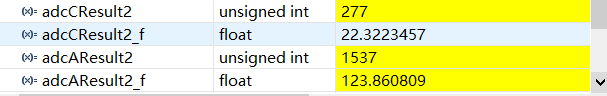
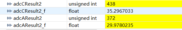
3.3V电压接入A6引脚时 adcAResult2显示为1537,而非4095,接入gnd显示372,而非0