LAUNCHXL-F28379D: 如何设置时钟来源

Part Number: LAUNCHXL-F28379D
Other Parts Discussed in Thread: CONTROLSUITE

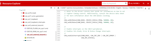
controlSUITE的CAN例程中(C:\ti\controlSUITE\device_support\F2837xD\v210\F2837xD_examples_Cpu1\can_external_transmit\cpu01),改了CANB为发送口,CAN调试器需要设置成250K才能通信成功。

发现sysctl.c代码中有void SysCtlClockSet(uint32_t ui32Config)函数,其中包含设置SYSCTL_OSCSRC_OSC1和2,以及SYSCTL_OSCSRC_XTAL的频率参数,例程源代码如下:

#define SYSCTL_OSCSRC_OSC2 0x00000000
#define SYSCTL_OSCSRC_XTAL 0x00010000
#define SYSCTL_OSCSRC_OSC1 0x00020000

/*...省略....*/
void
SysCtlClockSet(uint32_t ui32Config)
{
/*...省略....*/
if(clock_source != ClkCfgRegs.CLKSRCCTL1.bit.OSCCLKSRCSEL)
{
//Configure Oscillator
EALLOW;
switch (clock_source)
{
case ((uint32_t)SYSCTL_OSCSRC_OSC2 >> SYSCTL_OSCSRC_S):
ClkCfgRegs.CLKSRCCTL1.bit.INTOSC2OFF=0; // Turn on INTOSC2
ClkCfgRegs.CLKSRCCTL1.bit.OSCCLKSRCSEL = 0; // Clk Src = INTOSC2
break;

case ((uint32_t)SYSCTL_OSCSRC_XTAL >> SYSCTL_OSCSRC_S):
ClkCfgRegs.CLKSRCCTL1.bit.XTALOFF=0; // Turn on XTALOSC
ClkCfgRegs.CLKSRCCTL1.bit.OSCCLKSRCSEL = 1; // Clk Src = XTAL
break;

case ((uint32_t)SYSCTL_OSCSRC_OSC1 >> SYSCTL_OSCSRC_S):
ClkCfgRegs.CLKSRCCTL1.bit.OSCCLKSRCSEL = 2; // Clk Src = INTOSC1
break;
}
EDIS;
}
/*...省略....*/
}

控制板上采用的10Mhz晶振,从结果反推程序可能采用的是SYSCTL_OSCSRC_OSC1的参数,即20Mhz晶振。但是通过searchtext方式没有找到SysCtlClockSet函数的调用,这又陷入了死胡同。

请问系统时钟如何确定以及修改正确?

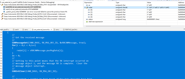
在下附上本人的程序,CAN用的12和17gpio

//.TI.ramfunc

//
// Included Files
//
#include "F28x_Project.h"
//#include "F2837xD_Ipc_drivers.h"
#include "inc/hw_types.h"
#include "inc/hw_memmap.h"
#include "inc/hw_can.h"
#include "driverlib/can.h"

//
// Globals
//

Uint16 on1 = 0;
Uint16 on2 = 0;
unsigned char txMsgData[4];
unsigned char rxMsgData[4];
tCANMsgObject sTXCANMessage;
tCANMsgObject sRXCANMessage;

//
// Function Prototypes
//


//
// Main
//
void main(void)

{

    InitSysCtrl();//20MXTAL_OSC DEVICE_SYSCLK_FREQ
//    EALLOW;
//   ClkCfgRegs.CLKSRCCTL1.bit.OSCCLKSRCSEL = 1; // Clk Src = XTAL
//    EDIS;
    InitGpio();
    GPIO_SetupPinMux(31, GPIO_MUX_CPU1, 0);
    GPIO_SetupPinOptions(31, GPIO_OUTPUT, GPIO_PUSHPULL);

    GPIO_SetupPinMux(17, GPIO_MUX_CPU1, 2); // GPIO17 - CANRXA
    GPIO_SetupPinMux(12, GPIO_MUX_CPU1, 2); // GPIO12 - CANTXA
    GPIO_SetupPinOptions(17, GPIO_INPUT, GPIO_ASYNC);
    GPIO_SetupPinOptions(12, GPIO_OUTPUT, GPIO_PUSHPULL);

    CANInit(CANB_BASE);
    CANClkSourceSelect(CANB_BASE, 0);
    CANBitRateSet(CANB_BASE, 200000000, 500000);

    DINT;

    InitPieCtrl();

    IER = 0x0000;
    IFR = 0x0000;

    InitPieVectTable();

    EINT;   // Enable Global interrupt INTM
    ERTM;   // Enable Global realtime interrupt DBGM

    CANEnable(CANB_BASE);

    sTXCANMessage.ui32MsgID = 0x0001;
    sTXCANMessage.ui32MsgIDMask = 0;
    sTXCANMessage.ui32Flags = 0;
    sTXCANMessage.ui32MsgLen = 4;
    sTXCANMessage.pucMsgData = txMsgData;

    txMsgData[0] = 0x12;
    txMsgData[1] = 0x34;
    txMsgData[2] = 0x56;
    txMsgData[3] = 0x78;

    for(;;)
    {
        on1 = ~on1;
        GPIO_WritePin(31, on1);
        CANMessageSet(CANB_BASE, 1, &sTXCANMessage, MSG_OBJ_TYPE_TX);
        DELAY_US(1000*250);
    }

}

//
// End of file
//

其中被屏蔽的三条语句:

// EALLOW;
// ClkCfgRegs.CLKSRCCTL1.bit.OSCCLKSRCSEL = 1; // Clk Src = XTAL
// EDIS;

是为了尝试修改时钟频率,但是还是不行

  • 好像我找到问题所在了。。

    F2837xD_SysCtrl.c中InitSysCtrl函数的最下方有:

    #ifdef _LAUNCHXL_F28379D
    InitSysPll(XTAL_OSC,IMULT_40,FMULT_0,PLLCLK_BY_2);
    #else
    InitSysPll(XTAL_OSC, IMULT_20, FMULT_0, PLLCLK_BY_2);
    #endif // _LAUNCHXL_F28379D

    但是例程里没有_LAUNCHXL_F28379D的定义,可以自己在.h文件里面定义一个:
    #define _LAUNCHXL_F28379D 1

    这样在void InitSysPll(Uint16 clock_source, Uint16 imult, Uint16 fmult, Uint16 divsel)函数里就配置正确了

  • 您好,

          感谢您的案例分享。

  • 是又有新问题,我在can_external_transmit原例程基础上,单独测试CANB的中断接收程序,can调试器每发送一次can数据(扩展帧 0x5555 Data:01 02 03 04),中断会连续执行两次。第一次中断在执行status = CANIntStatus(CANB_BASE, CAN_INT_STS_CAUSE);时,status 的值 为CAN_INT_INT0ID_STATUS即0x10;

    第二次中断,则status的值为RX_MSG_OBJ_ID即1,此时开始执行CANMessageGet(CANB_BASE, RX_MSG_OBJ_ID, &sRXCANMessage, true);

    我的判断依据是通过设置计数器变量xx,在中断执行的开头自增一次,只有在执行完CANMessageGet(CANB_BASE, RX_MSG_OBJ_ID, &sRXCANMessage, true);语句后xx清零。

    具体代码如下:

    //###########################################################################
    //
    // FILE:   can_external_transmit.c
    //
    // TITLE:  Example to demonstrate CAN external transmission
    //
    //! \addtogroup cpu01_example_list
    //! <h1>CAN-A to CAN-B External Transmit (can_external_transmit)</h1>
    //!
    //! This example initializes CAN module A and CAN module B for external
    //! communication. CAN-A module is setup to transmit incrementing data for "n"
    //! number of times to the CAN-B module, where "n" is the value of TXCOUNT.
    //! CAN-B module is setup to trigger an interrupt service routine (ISR) when
    //! data is received. An error flag will be set if the transmitted data doesn't
    //! match the received data.
    //!
    //! \note Both CAN modules on the device need to be
    //!       connected to each other via CAN transceivers.
    //!
    //! \b External \b Connections \n
    //!  - CANA is on GPIO31 (CANTXA) and GPIO30 (CANRXA)
    //!  - CANB is on GPIO8 (CANTXB) and GPIO10 (CANRXB)
    //!
    //! \b Watch \b Variables \n
    //!  - TXCOUNT - Adjust to set the number of messages to be transmitted
    //!  - txMsgCount - A counter for the number of messages sent
    //!  - rxMsgCount - A counter for the number of messages received
    //!  - txMsgData - An array with the data being sent
    //!  - rxMsgData - An array with the data that was received
    //!  - errorFlag - A flag that indicates an error has occurred
    //!
    //
    //###########################################################################
    // $TI Release: F2837xD Support Library v210 $
    // $Release Date: Tue Nov  1 14:46:15 CDT 2016 $
    // $Copyright: Copyright (C) 2013-2016 Texas Instruments Incorporated -
    //             http://www.ti.com/ ALL RIGHTS RESERVED $
    //###########################################################################
    
    //
    // Included Files
    //
    #include "F28x_Project.h"     // Device Headerfile and Examples Include File
    #include <stdint.h>
    #include <stdbool.h>
    #include "inc/hw_types.h"
    #include "inc/hw_memmap.h"
    #include "inc/hw_can.h"
    #include "driverlib/can.h"
    
    //
    // Defines
    //
    #define TXCOUNT  100
    #define MSG_DATA_LENGTH    4
    #define TX_MSG_OBJ_ID    1
    #define RX_MSG_OBJ_ID    1
    
    //
    // Globals
    //
    volatile unsigned long i;
    volatile uint32_t txMsgCount = 0;
    volatile uint32_t rxMsgCount = 0;
    volatile uint32_t errorFlag = 0;
    unsigned char txMsgData[4];
    unsigned char rxMsgData[4];
    tCANMsgObject sTXCANMessage;
    tCANMsgObject sRXCANMessage;
    
    unsigned char rxdat[4]={0};
    unsigned char xx = 0;
    //
    // Function Prototypes
    //
    __interrupt void canbISR(void);
    
    //
    // Main
    //
    void main(void)
    {
        //
        // Initialize System Control:
        // PLL, WatchDog, enable Peripheral Clocks
        //
        InitSysCtrl();
    
        //
        // Initialize GPIO and configure GPIO pins for CANTX/CANRX
        // on module A and B
        //
        InitGpio();
    
        //
        // Setup GPIO pin mux for CAN-A TX/RX and CAN-B TX/RX
        //
        GPIO_SetupPinMux(30, GPIO_MUX_CPU1, 1); //GPIO30 -  CANRXA
        GPIO_SetupPinOptions(30, GPIO_INPUT, GPIO_ASYNC);
        GPIO_SetupPinMux(31, GPIO_MUX_CPU1, 1); //GPIO31 - CANTXA
        GPIO_SetupPinOptions(31, GPIO_OUTPUT, GPIO_PUSHPULL);
        GPIO_SetupPinMux(17, GPIO_MUX_CPU1, 2); //GPIO10 -  CANRXB
        GPIO_SetupPinOptions(17, GPIO_INPUT, GPIO_ASYNC);
        GPIO_SetupPinMux(12, GPIO_MUX_CPU1, 2);  //GPIO8 - CANTXB
        GPIO_SetupPinOptions(12, GPIO_OUTPUT, GPIO_PUSHPULL);
    
        //
        // Initialize the CAN controllers
        //
        CANInit(CANA_BASE);
        CANInit(CANB_BASE);
    
        //
        // Setup CAN to be clocked off the PLL output clock
        //
        CANClkSourceSelect(CANA_BASE, 0);   // 500kHz CAN-Clock
        CANClkSourceSelect(CANB_BASE, 0);   // 500kHz CAN-Clock
    
        //
        // Set up the CAN bus bit rate to 500kHz for each module
        // This function sets up the CAN bus timing for a nominal configuration.
        // You can achieve more control over the CAN bus timing by using the
        // function CANBitTimingSet() instead of this one, if needed.
        // Additionally, consult the device data sheet for more information about
        // the CAN module clocking.
        //
        CANBitRateSet(CANA_BASE, 200000000, 500000);
        CANBitRateSet(CANB_BASE, 200000000, 500000);
    
        //
        // Enable interrupts on the CAN B peripheral.
        //
        CANIntEnable(CANB_BASE, CAN_INT_MASTER | CAN_INT_ERROR | CAN_INT_STATUS);
    
        //
        // Clear all interrupts and initialize PIE vector table:
        // Disable CPU interrupts
        //
        DINT;
    
        //
        // Initialize the PIE control registers to their default state.
        // The default state is all PIE interrupts disabled and flags
        // are cleared.
        //
        InitPieCtrl();
    
        //
        // Disable CPU interrupts and clear all CPU interrupt flags
        //
        IER = 0x0000;
        IFR = 0x0000;
    
        //
        // Initialize the PIE vector table with pointers to the shell Interrupt
        // Service Routines (ISR).
        // This will populate the entire table, even if the interrupt
        // is not used in this example.  This is useful for debug purposes.
        //
        InitPieVectTable();
    
        //
        // Interrupts that are used in this example are re-mapped to
        // ISR functions found within this file.
        // This registers the interrupt handler in PIE vector table.
        //
        EALLOW;
        PieVectTable.CANB0_INT = canbISR;
        EDIS;
    
        //
        // Enable the CAN-B interrupt on the processor (PIE).
        //
        PieCtrlRegs.PIEIER9.bit.INTx7 = 1;
        IER |= M_INT9;
        EINT;
    
        //
        // Enable the CAN-B interrupt signal
        //
        CANGlobalIntEnable(CANB_BASE, CAN_GLB_INT_CANINT0);
    
        //
        // Initialize the transmit message object used for sending CAN messages.
        // Message Object Parameters:
        //      Message Identifier: 0x5555
        //      Message ID Mask: 0x0
        //      Message Object Flags: None
        //      Message Data Length: 4 Bytes
        //      Message Transmit data: txMsgData
        //
        sTXCANMessage.ui32MsgID = 0x5555;
        sTXCANMessage.ui32MsgIDMask = 0;
        sTXCANMessage.ui32Flags = 0;
        sTXCANMessage.ui32MsgLen = MSG_DATA_LENGTH;
        sTXCANMessage.pucMsgData = txMsgData;
    
        //
        // Initialize the receive message object used for receiving CAN messages.
        // Message Object Parameters:
        //      Message Identifier: 0x5555
        //      Message ID Mask: 0x0
        //      Message Object Flags: Receive Interrupt
        //      Message Data Length: 4 Bytes
        //      Message Receive data: rxMsgData
        //
        sRXCANMessage.ui32MsgID = 0x5555;
        sRXCANMessage.ui32MsgIDMask = 0;
        sRXCANMessage.ui32Flags = MSG_OBJ_RX_INT_ENABLE;
        sRXCANMessage.ui32MsgLen = MSG_DATA_LENGTH;
        sRXCANMessage.pucMsgData = rxMsgData;
        CANMessageSet(CANB_BASE, RX_MSG_OBJ_ID, &sRXCANMessage,
                      MSG_OBJ_TYPE_RX);
    
        //
        // Initialize the transmit message object data buffer to be sent
        //
        txMsgData[0] = 0x12;
        txMsgData[1] = 0x34;
        txMsgData[2] = 0x56;
        txMsgData[3] = 0x78;
    
        //
        // Start CAN module A and B operations
        //
        CANEnable(CANA_BASE);
        CANEnable(CANB_BASE);
    
        //
        // Transmit messages from CAN-A to CAN-B
        //
    //    for(i = 0; i < TXCOUNT; i++)
        for( ;  ;  )
        {
            //
            // Check the error flag to see if errors occurred
            //
            /*if(errorFlag)
            {
                asm("   ESTOP0");
            }*/
    
            //
            // Verify that the number of transmitted messages equal the number of
            // messages received before sending a new message
            //
           /* if(txMsgCount == rxMsgCount)
            {*/
                //
                // Transmit Message
                //
                CANMessageSet(CANA_BASE, TX_MSG_OBJ_ID, &sTXCANMessage,
                              MSG_OBJ_TYPE_TX);
    
            /*    txMsgCount++;
            }*/
            /*else
            {
                errorFlag = 1;
            }*/
    
            //
            // Delay 0.25 second before continuing
            //
            DELAY_US(1000 * 250);
    
            //
            // Increment the value in the transmitted message data.
            //
            txMsgData[0] += 0x01;
            txMsgData[1] += 0x01;
            txMsgData[2] += 0x01;
            txMsgData[3] += 0x01;
        }
    
        //
        // Stop application
        //
        asm("   ESTOP0");
    }
    
    //
    // CAN B ISR - The interrupt service routine called when a CAN interrupt is
    //             triggered on CAN module B.
    //
    __interrupt void
    canbISR(void)
    {
        uint32_t status;
        int i=0;
        xx++;
        //
        // Read the CAN-B interrupt status to find the cause of the interrupt
        //
        status = CANIntStatus(CANB_BASE, CAN_INT_STS_CAUSE);
    
        //
        // If the cause is a controller status interrupt, then get the status
        //
        if(status == CAN_INT_INT0ID_STATUS)
        {
            //
            // Read the controller status.  This will return a field of status
            // error bits that can indicate various errors.  Error processing
            // is not done in this example for simplicity.  Refer to the
            // API documentation for details about the error status bits.
            // The act of reading this status will clear the interrupt.
            //
            status = CANStatusGet(CANB_BASE, CAN_STS_CONTROL);
    //        CANMessageGet(CANB_BASE, RX_MSG_OBJ_ID, &sRXCANMessage, true);
    
            //
            // Check to see if an error occurred.
            //
            if(((status  & ~(CAN_ES_RXOK)) != 7) &&
               ((status  & ~(CAN_ES_RXOK)) != 0))
            {
                //
                // Set a flag to indicate some errors may have occurred.
                //
                errorFlag = 1;
            }
        }
        //
        // Check if the cause is the CAN-B receive message object 1
        //
        else if(status == RX_MSG_OBJ_ID)
        {
            //
            // Get the received message
            //
            CANMessageGet(CANB_BASE, RX_MSG_OBJ_ID, &sRXCANMessage, true);
            for(i = 0;i < 4;i++)
            {
                rxdat[i] = sRXCANMessage.pucMsgData[i];
            }
            xx = 0;
            //
            // Getting to this point means that the RX interrupt occurred on
            // message object 1, and the message RX is complete.  Clear the
            // message object interrupt.
            //
            CANIntClear(CANB_BASE, RX_MSG_OBJ_ID);
    
            //
            // Increment a counter to keep track of how many messages have been
            // received. In a real application this could be used to set flags to
            // indicate when a message is received.
            //
            rxMsgCount++;
    
            //
            // Since the message was received, clear any error flags.
            //
            errorFlag = 0;
        }
        //
        // If something unexpected caused the interrupt, this would handle it.
        //
        else
        {
            //
            // Spurious interrupt handling can go here.
            //
        }
    
        //
        // Clear the global interrupt flag for the CAN interrupt line
        //
        CANGlobalIntClear(CANB_BASE, CAN_GLB_INT_CANINT0);
    
        //
        // Acknowledge this interrupt located in group 9
        //
        PieCtrlRegs.PIEACK.all = PIEACK_GROUP9;
    }
    
    //
    // End of File
    //
    

    仿真截图,当程序执行到CANMessageGet函数时,xx和data里的数据

  • 把CANIntEnable(CANB_BASE, CAN_INT_MASTER | CAN_INT_ERROR | CAN_INT_STATUS);函数中的“| CAN_INT_STATUS”删掉就可以了。。但是没搞懂原因。

    请问2837x中像是“CANIntEnable()”这种函数的使用说明手册哪里有下载啊?只找到“TMS320F2837xD Dual-Core Real-Time Microcontrollers Technical Reference Manual”还是英文的。。根本没有函数API手册啊

  • 您好,

          没有API说明,只能参考代码中的注释。  

          can_ex3_external_transmit.c (ti.com)