This thread has been locked.

If you have a related question, please click the "Ask a related question" button in the top right corner. The newly created question will be automatically linked to this question.

芯片用的是msp430g2533,温度传感器用的tmp101,现在用官方例程,iic两路信号没有波形,把低功耗注释掉,波形正常,但是UCB0RXBUF寄存器的数据始终是0x80,求解答,谢谢,程序如下

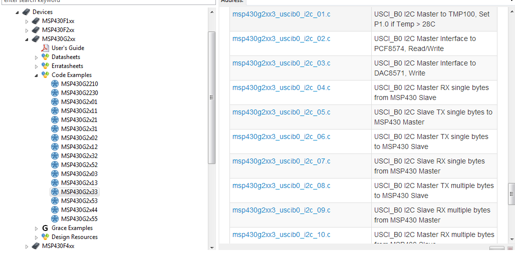
Other Parts Discussed in Thread: MSP430G2533, TMP101

#include <msp430.h>

unsigned int RxByteCtr;
unsigned int RxWord;

int main(void)
{
WDTCTL = WDTPW + WDTHOLD; // Stop WDT
P1DIR |= BIT0; // P1.0 output
P1SEL |= BIT6 + BIT7; // Assign I2C pins to USCI_B0
P1SEL2|= BIT6 + BIT7; // Assign I2C pins to USCI_B0
UCB0CTL1 |= UCSWRST; // Enable SW reset
UCB0CTL0 = UCMST + UCMODE_3 + UCSYNC; // I2C Master, synchronous mode
UCB0CTL1 = UCSSEL_2 + UCSWRST; // Use SMCLK, keep SW reset
UCB0BR0 = 12; // fSCL = SMCLK/12 = ~100kHz
UCB0BR1 = 0;
UCB0I2CSA = 0x4e; // Set slave address
UCB0CTL1 &= ~UCSWRST; // Clear SW reset, resume operation
IE2 |= UCB0RXIE; // Enable RX interrupt
TACTL = TASSEL_2 + MC_2; // SMCLK, contmode

while (1)
{
RxByteCtr = 2; // Load RX byte counter
UCB0CTL1 |= UCTXSTT; // I2C start condition
__bis_SR_register(CPUOFF + GIE); // Enter LPM0, enable interrupts
// Remain in LPM0 until all data
// is RX'd

if (RxWord < 0x1d00) // >28C?
P1OUT &= ~0x01; // No, P1.0 = 0
else
P1OUT |= 0x01; // Yes, P1.0 = 1

__disable_interrupt();
TACCTL0 |= CCIE; // TACCR0 interrupt enabled
__bis_SR_register(CPUOFF + GIE); // Enter LPM0, enable interrupts
// Remain in LPM0 until TACCR0
// interrupt occurs
TACCTL0 &= ~CCIE; // TACCR0 interrupt disabled
}
}

#pragma vector = TIMER0_A0_VECTOR
__interrupt void TA0_ISR(void)
{
__bic_SR_register_on_exit(CPUOFF); // Exit LPM0
}

// The USCIAB0TX_ISR is structured such that it can be used to receive any
// 2+ number of bytes by pre-loading RxByteCtr with the byte count.
#pragma vector = USCIAB0TX_VECTOR
__interrupt void USCIAB0TX_ISR(void)
{
RxByteCtr--; // Decrement RX byte counter

if (RxByteCtr)
{
RxWord = (unsigned int)UCB0RXBUF << 8; // Get received byte
if (RxByteCtr == 1) // Only one byte left?
UCB0CTL1 |= UCTXSTP; // Generate I2C stop condition
}
else
{
RxWord |= UCB0RXBUF; // Get final received byte,
// Combine MSB and LSB
__bic_SR_register_on_exit(CPUOFF); // Exit LPM0
}
}

  • 这个是官方例程吗?

    个人觉得逻辑上有错误,标注在你的代码中。

    不妨在你中断函数设置断点,看看程序运行是否如我的推测。谢谢!

    yao wang5 说:

    #include <msp430.h>

    unsigned int RxByteCtr;
    unsigned int RxWord;

    int main(void)
    {
    WDTCTL = WDTPW + WDTHOLD; // Stop WDT
    P1DIR |= BIT0; // P1.0 output
    P1SEL |= BIT6 + BIT7; // Assign I2C pins to USCI_B0
    P1SEL2|= BIT6 + BIT7; // Assign I2C pins to USCI_B0
    UCB0CTL1 |= UCSWRST; // Enable SW reset
    UCB0CTL0 = UCMST + UCMODE_3 + UCSYNC; // I2C Master, synchronous mode
    UCB0CTL1 = UCSSEL_2 + UCSWRST; // Use SMCLK, keep SW reset
    UCB0BR0 = 12; // fSCL = SMCLK/12 = ~100kHz
    UCB0BR1 = 0;
    UCB0I2CSA = 0x4e; // Set slave address
    UCB0CTL1 &= ~UCSWRST; // Clear SW reset, resume operation
    IE2 |= UCB0RXIE; // Enable RX interrupt
    TACTL = TASSEL_2 + MC_2; // SMCLK, contmode

    while (1)
    {
    RxByteCtr = 2; // Load RX byte counter  //每次运行到这里,这个变量都强行赋值为2 
    UCB0CTL1 |= UCTXSTT; // I2C start condition
    __bis_SR_register(CPUOFF + GIE); // Enter LPM0, enable interrupts

    // 如果I2C接收到数据中断,其值应该只获取到1byte  程序继续往下运行。 你可以发现你获取的值应该就是一个BYTE  后又回到RxByteCtr = 2;这个代码

    // Remain in LPM0 until all data
    // is RX'd

    if (RxWord < 0x1d00) // >28C?
    P1OUT &= ~0x01; // No, P1.0 = 0
    else
    P1OUT |= 0x01; // Yes, P1.0 = 1

    __disable_interrupt();  // 这个可以屏蔽 
    TACCTL0 |= CCIE; // TACCR0 interrupt enabled  //这个定时还有其它配置没有
    __bis_SR_register(CPUOFF + GIE); // Enter LPM0, enable interrupts
    // Remain in LPM0 until TACCR0
    // interrupt occurs
    TACCTL0 &= ~CCIE; // TACCR0 interrupt disabled
    }
    }

    #pragma vector = TIMER0_A0_VECTOR
    __interrupt void TA0_ISR(void)
    {
    __bic_SR_register_on_exit(CPUOFF); // Exit LPM0
    }

    // The USCIAB0TX_ISR is structured such that it can be used to receive any
    // 2+ number of bytes by pre-loading RxByteCtr with the byte count.
    #pragma vector = USCIAB0TX_VECTOR
    __interrupt void USCIAB0TX_ISR(void)
    {
    RxByteCtr--; // Decrement RX byte counter

    if (RxByteCtr)
    {
    RxWord = (unsigned int)UCB0RXBUF << 8; // Get received byte
    if (RxByteCtr == 1) // Only one byte left?
    UCB0CTL1 |= UCTXSTP; // Generate I2C stop condition
    }
    else
    {
    RxWord |= UCB0RXBUF; // Get final received byte,
    // Combine MSB and LSB
    __bic_SR_register_on_exit(CPUOFF); // Exit LPM0
    }
    }

  • 现在按你说的操作,早中断函数设置断点,波形和寄存器都是对的,请问,程序该怎么改呢?谢谢

  • 刚才设了断点运行正常,同样的程序,现在设置断点,程序不停止,也没有波形输出,是什么原因?ccs编译器的问题么?

  • 改成这样测试一下,看看结果是否正确。Timer 配置不完整,你可以在这里换成一个比较长的延时看看,这个是等待I2C数据接收完成。

    yao wang5 说:

    #include <msp430.h>

    unsigned int RxByteCtr;
    unsigned int RxWord;

    int main(void)
    {
    WDTCTL = WDTPW + WDTHOLD; // Stop WDT
    P1DIR |= BIT0; // P1.0 output
    P1SEL |= BIT6 + BIT7; // Assign I2C pins to USCI_B0
    P1SEL2|= BIT6 + BIT7; // Assign I2C pins to USCI_B0
    UCB0CTL1 |= UCSWRST; // Enable SW reset
    UCB0CTL0 = UCMST + UCMODE_3 + UCSYNC; // I2C Master, synchronous mode
    UCB0CTL1 = UCSSEL_2 + UCSWRST; // Use SMCLK, keep SW reset
    UCB0BR0 = 12; // fSCL = SMCLK/12 = ~100kHz
    UCB0BR1 = 0;
    UCB0I2CSA = 0x4e; // Set slave address
    UCB0CTL1 &= ~UCSWRST; // Clear SW reset, resume operation

    RxByteCtr = 2; // Load RX byte counter

    IE2 |= UCB0RXIE; // Enable RX interrupt
    TACTL = TASSEL_2 + MC_2; // SMCLK, contmode

    while (1)
    {
    //RxByteCtr = 2; // Load RX byte counter
    UCB0CTL1 |= UCTXSTT; // I2C start condition
    //__bis_SR_register(CPUOFF + GIE); // Enter LPM0, enable interrupts
    // Remain in LPM0 until all data
    // is RX'd

    if (RxWord < 0x1d00) // >28C?
    P1OUT &= ~0x01; // No, P1.0 = 0
    else
    P1OUT |= 0x01; // Yes, P1.0 = 1

    //__disable_interrupt();
    TACCTL0 |= CCIE; // TACCR0 interrupt enabled
    __bis_SR_register(CPUOFF + GIE); // Enter LPM0, enable interrupts
    // Remain in LPM0 until TACCR0
    // interrupt occurs
    TACCTL0 &= ~CCIE; // TACCR0 interrupt disabled
    }
    }

    #pragma vector = TIMER0_A0_VECTOR
    __interrupt void TA0_ISR(void)
    {
    __bic_SR_register_on_exit(CPUOFF); // Exit LPM0
    }

    // The USCIAB0TX_ISR is structured such that it can be used to receive any
    // 2+ number of bytes by pre-loading RxByteCtr with the byte count.
    #pragma vector = USCIAB0TX_VECTOR
    __interrupt void USCIAB0TX_ISR(void)
    {
    RxByteCtr--; // Decrement RX byte counter

    if (RxByteCtr)
    {
    RxWord = (unsigned int)UCB0RXBUF << 8; // Get received byte
    if (RxByteCtr == 1) // Only one byte left?
    UCB0CTL1 |= UCTXSTP; // Generate I2C stop condition
    }
    else
    {
    RxWord |= UCB0RXBUF; // Get final received byte,
    // Combine MSB and LSB
    __bic_SR_register_on_exit(CPUOFF); // Exit LPM0

    RxByteCtr = 2; // Load RX byte counter
    }
    }

  • 这个出了波形,凡是波形不正确,寄存器里的值还是0x80。用刚才测试的程序,没有波形了并且scl被拉低了,是这颗芯片msp430g2533的iic存在问题么?时好时坏?有没有这颗芯片不用中断的iic的例程呢?

  • 在MSPWARE中有很多I2C例程,建议你还是跑一下例程先。如上图所示,CCS环境中。

  • 你贴的好像是TI给官方例程,我刚刚检查一下逻辑,是没有问题的。如果波形出不来是因为进入低功耗的原因吗?

    那我建议如下更改:

    #include <msp430.h>

    unsigned int RxByteCtr;
    unsigned int RxWord;

    int main(void)
    {
    WDTCTL = WDTPW + WDTHOLD; // Stop WDT
    P1DIR |= BIT0; // P1.0 output
    P1SEL |= BIT6 + BIT7; // Assign I2C pins to USCI_B0
    P1SEL2|= BIT6 + BIT7; // Assign I2C pins to USCI_B0
    UCB0CTL1 |= UCSWRST; // Enable SW reset
    UCB0CTL0 = UCMST + UCMODE_3 + UCSYNC; // I2C Master, synchronous mode
    UCB0CTL1 = UCSSEL_2 + UCSWRST; // Use SMCLK, keep SW reset
    UCB0BR0 = 12; // fSCL = SMCLK/12 = ~100kHz
    UCB0BR1 = 0;
    UCB0I2CSA = 0x4e; // Set slave address
    UCB0CTL1 &= ~UCSWRST; // Clear SW reset, resume operation
    IE2 |= UCB0RXIE; // Enable RX interrupt
    TACTL = TASSEL_2 + MC_2; // SMCLK, contmode

    while (1)
    {
    RxByteCtr = 2; // Load RX byte counter
    UCB0CTL1 |= UCTXSTT; // I2C start condition
    //__bis_SR_register(CPUOFF + GIE); // Enter LPM0, enable interrupts//不进入低功耗状态
    // Remain in LPM0 until all data
    // is RX'd

    while(RxByteCtr); //等待数据接收完毕 两个字节 

    if (RxWord < 0x1d00) // >28C?
    P1OUT &= ~0x01; // No, P1.0 = 0
    else
    P1OUT |= 0x01; // Yes, P1.0 = 1

    __disable_interrupt();
    TACCTL0 |= CCIE; // TACCR0 interrupt enabled
    __bis_SR_register(CPUOFF + GIE); // Enter LPM0, enable interrupts
    // Remain in LPM0 until TACCR0
    // interrupt occurs
    TACCTL0 &= ~CCIE; // TACCR0 interrupt disabled
    }
    }

    #if defined(__TI_COMPILER_VERSION__) || defined(__IAR_SYSTEMS_ICC__)
    #pragma vector = TIMER0_A0_VECTOR
    __interrupt void TA0_ISR(void)
    #elif defined(__GNUC__)
    void __attribute__ ((interrupt(TIMER0_A0_VECTOR))) TA0_ISR (void)
    #else
    #error Compiler not supported!
    #endif
    {
    __bic_SR_register_on_exit(CPUOFF); // Exit LPM0
    }

    // The USCIAB0TX_ISR is structured such that it can be used to receive any
    // 2+ number of bytes by pre-loading RxByteCtr with the byte count.
    #if defined(__TI_COMPILER_VERSION__) || defined(__IAR_SYSTEMS_ICC__)
    #pragma vector = USCIAB0TX_VECTOR
    __interrupt void USCIAB0TX_ISR(void)
    #elif defined(__GNUC__)
    void __attribute__ ((interrupt(USCIAB0TX_VECTOR))) USCIAB0TX_ISR (void)
    #else
    #error Compiler not supported!
    #endif
    {
    RxByteCtr--; // Decrement RX byte counter

    if (RxByteCtr)
    {
    RxWord = (unsigned int)UCB0RXBUF << 8; // Get received byte
    if (RxByteCtr == 1) // Only one byte left?
    UCB0CTL1 |= UCTXSTP; // Generate I2C stop condition
    }
    else
    {
    RxWord |= UCB0RXBUF; // Get final received byte,
    // Combine MSB and LSB
    //__bic_SR_register_on_exit(CPUOFF); // Exit LPM0
    }
    }

  • 都还是老样子,没有波形,寄存器里的数值也不变,是不是芯片的iic硬件有问题?能不能提供一下用IO口模拟iic读取tmp101温度的例程,来测试下p1.6和p1.7是不是正常,谢谢

  • 在中断函数中设置断点试试?程序运行停在什么地方?可以把后面定时器进入LPM0也屏蔽看看。

  • 设置了断点程序不停,每次手动暂停程序都停在这里while(RxByteCtr); //等待数据接收完毕 两个字节

    还是没有波形

  • 那说明没有进入中断服务函数中,这个你需要检查一下你的外围电路是否存在异常。

    把SCL SDA两者波形同时抓出来,第一看看主设备有没有指令发出,第二在确认从设备是否效应。

  • 偶尔是对的,外围电路检查过没问题。