This thread has been locked.
If you have a related question, please click the "Ask a related question" button in the top right corner. The newly created question will be automatically linked to this question.
串口接收数据会错位,怎么能完整的接收一帧数据
user5779306 说:串口接收数据会错位
能否详细说一下您的问题或者给出相关代码?是否有参考TI例程?
#if defined(__TI_COMPILER_VERSION__) || defined(__IAR_SYSTEMS_ICC__) #pragma vector=USCI_A0_VECTOR __interrupt #elif defined(__GNUC__) __attribute__((interrupt(USCI_A1_VECTOR))) #endif void UART_ISR(void) { uint8_t res; MODS_ReciveNew(EUSCI_A_UART_receiveData(EUSCI_A0_BASE)); EUSCI_A_UART_clearInterrupt(EUSCI_A0_BASE, EUSCI_A_UART_RECEIVE_INTERRUPT); } void MODS_ReciveNew(uint8_t _byte) { /* 3.5个字符的时间间隔,只是用在RTU模式下面,因为RTU模式没有开始符和结束符, 两个数据包之间只能靠时间间隔来区分,Modbus定义在不同的波特率下,间隔时间是不一样的, 所以就是3.5个字符的时间,波特率高,这个时间间隔就小,波特率低,这个时间间隔相应就大 4800 = 7.297ms 9600 = 3.646ms 19200 = 1.771ms 38400 = 0.885ms */ uint32_t timeout; g_mods_timeout = 0; timeout = 35000000 / SBAUD485; /* 计算超时时间,单位us 35000000*/ /* 硬件定时中断,定时精度us 硬件定时器1用于ADC, 定时器2用于Modbus */ //TB0CCR0 = 0; TIMER_B_INIT(250);// 137 3.646ms TB0CCR0 = 0; if (g_tModS.RxCount < S_RX_BUF_SIZE) { g_tModS.RxBuf[g_tModS.RxCount++] = _byte; } }
请您以下面的方式上传一下代码
void Clock_Init(void)
{

    GPIO_setAsPeripheralModuleFunctionInputPin(GPIO_PORT_PJ,GPIO_PIN5,GPIO_PRIMARY_MODULE_FUNCTION);
    GPIO_setAsPeripheralModuleFunctionOutputPin(GPIO_PORT_PJ,GPIO_PIN4,GPIO_PRIMARY_MODULE_FUNCTION);
    CS_turnOnLFXT(CS_LFXT_DRIVE_0);
    CS_initClockSignal(CS_ACLK, CS_LFXTCLK_SELECT, CS_CLOCK_DIVIDER_1);
    CS_setDCOFreq(CS_DCORSEL_0, CS_DCOFSEL_6); //设置dco 1mhz
    CS_initClockSignal(CS_SMCLK,CS_DCOCLK_SELECT,CS_CLOCK_DIVIDER_8);//设置 smclk时钟来源为 dco
    CS_initClockSignal(CS_MCLK,CS_DCOCLK_SELECT,CS_CLOCK_DIVIDER_1);
}
void TIMER_B_INIT(uint16_t perd)
{

    Timer_B_initUpModeParam Tiemr_B_initUpModeStucture; //定义结构体变量
    Tiemr_B_initUpModeStucture.clockSource = TIMER_B_CLOCKSOURCE_SMCLK; //tiemr 时钟
    Tiemr_B_initUpModeStucture.clockSourceDivider = TIMER_B_CLOCKSOURCE_DIVIDER_10;//分频50k
    Tiemr_B_initUpModeStucture.timerPeriod = perd;// 计数值
    Tiemr_B_initUpModeStucture.captureCompareInterruptEnable_CCR0_CCIE = TIMER_B_CCIE_CCR0_INTERRUPT_ENABLE;//使能中断
    Tiemr_B_initUpModeStucture.timerClear = TIMER_B_DO_CLEAR;
    Tiemr_B_initUpModeStucture.startTimer = true;//开始计数
    Timer_B_initUpMode(TIMER_B0_BASE, &Tiemr_B_initUpModeStucture);//初始化
    Timer_B_enableCaptureCompareInterrupt(TIMER_B0_BASE,TIMER_B_CAPTURECOMPARE_REGISTER_0);
}

void UART_Init(uint32_t Baudrate)
{

    GPIO_setAsPeripheralModuleFunctionInputPin(GPIO_PORT_P4,GPIO_PIN3,GPIO_PRIMARY_MODULE_FUNCTION);
    GPIO_setAsPeripheralModuleFunctionOutputPin(GPIO_PORT_P4,GPIO_PIN2,GPIO_PRIMARY_MODULE_FUNCTION);

    EUSCI_A_UART_initParam EUSCI_A_UART_initStucture;
    EUSCI_A_UART_initStucture.selectClockSource = EUSCI_A_UART_CLOCKSOURCE_SMCLK;
    EUSCI_A_UART_initStucture.overSampling = EUSCI_A_UART_LOW_FREQUENCY_BAUDRATE_GENERATION;// UCOC16
    switch (Baudrate)
    {
     case 4800:
         EUSCI_A_UART_initStucture.selectClockSource = EUSCI_A_UART_CLOCKSOURCE_ACLK;
         ucbr = 6;
         ucbrs = 0xee;
         ucbrf = 0;
         break;
    case 9600:
        EUSCI_A_UART_initStucture.selectClockSource = EUSCI_A_UART_CLOCKSOURCE_ACLK;
        ucbr = 3;
        ucbrs = 0x92;
        ucbrf = 0;
        break;
    case 19200:
        EUSCI_A_UART_initStucture.overSampling = EUSCI_A_UART_OVERSAMPLING_BAUDRATE_GENERATION;
        ucbr = 3;
        ucbrs = 0x2;
        ucbrf = 4;
        break;
    case 57600:
        ucbr = 17;
        ucbrs = 0x4a;
        ucbrf = 0;
        break;
    case 115200:
        ucbr = 8;
        ucbrs = 0xd6;
        ucbrf = 0;
        break;
    default: break;
    }
    EUSCI_A_UART_initStucture.clockPrescalar = ucbr;//UCBRx
    EUSCI_A_UART_initStucture.firstModReg = ucbrf;//第一级调节器 查表//UCBRFx
    EUSCI_A_UART_initStucture.secondModReg = ucbrs;//UCBRSx
    EUSCI_A_UART_initStucture.parity =  EUSCI_A_UART_NO_PARITY;//校验选择 无校验
    EUSCI_A_UART_initStucture.msborLsbFirst = EUSCI_A_UART_LSB_FIRST;//低位有效
    EUSCI_A_UART_initStucture.numberofStopBits = EUSCI_A_UART_ONE_STOP_BIT;//一位停止位
    EUSCI_A_UART_initStucture.uartMode = EUSCI_A_UART_MODE;//uart模式  00b=UART模式 01b=空闲线路多处理器模式 10b=地址位多处理器模式 11b=具有自动波特率检测的UART模式
    if (STATUS_FAIL == EUSCI_A_UART_init(EUSCI_A0_BASE, &EUSCI_A_UART_initStucture))
    {
        return;
    }
    EUSCI_A_UART_init(EUSCI_A0_BASE,&EUSCI_A_UART_initStucture);
    EUSCI_A_UART_enable(EUSCI_A0_BASE);
    EUSCI_A_UART_enableInterrupt(EUSCI_A0_BASE,EUSCI_A_UART_RECEIVE_INTERRUPT);
}
#if defined(__TI_COMPILER_VERSION__) || defined(__IAR_SYSTEMS_ICC__)
#pragma vector=USCI_A0_VECTOR
__interrupt
#elif defined(__GNUC__)
__attribute__((interrupt(USCI_A1_VECTOR)))
#endif
void UART_ISR(void)
{


      MODS_ReciveNew(EUSCI_A_UART_receiveData(EUSCI_A0_BASE));
       EUSCI_A_UART_clearInterrupt(EUSCI_A0_BASE, EUSCI_A_UART_RECEIVE_INTERRUPT);

}
void MODS_ReciveNew(uint8_t _byte)
{
	/*
		3.5个字符的时间间隔,只是用在RTU模式下面,因为RTU模式没有开始符和结束符,
		两个数据包之间只能靠时间间隔来区分,Modbus定义在不同的波特率下,间隔时间是不一样的,
		所以就是3.5个字符的时间,波特率高,这个时间间隔就小,波特率低,这个时间间隔相应就大

		4800  = 7.297ms
		9600  = 3.646ms
		19200  = 1.771ms
		38400  = 0.885ms
	*/
	uint32_t timeout;

	g_mods_timeout = 0;

	timeout = 35000000 / SBAUD485;			/* 计算超时时间,单位us 35000000*/

	/* 硬件定时中断,定时精度us 硬件定时器1用于ADC, 定时器2用于Modbus */
	//TB0CCR0 = 0;
	TIMER_B_INIT(250);// 137 3.646ms
    TB0CCR0 = 0;

	if (g_tModS.RxCount < S_RX_BUF_SIZE)
	{
		g_tModS.RxBuf[g_tModS.RxCount++] = _byte;
	}
}
看您的代码,中断服务程序内需要处理的有点太多了,建议减少其中需要处理的内容,先只处理数据试试
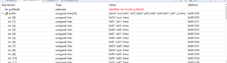
这是我发送了两次01 03 00 01 00 01 D5 CA 的接收结果,第一次只收到了帧尾,第二次才完整的接收了一帧数据
user5779306 说:第二次才完整的接收了一帧数据
谢谢反馈,是否还有数据错位的情况?
user5779306 说:第一次只收到了帧尾,
数据接收不全有可能是接收数据溢出了或者是其他中断、代码引起的
接收数据溢出该怎么解决,我刚才又测试了一下,经常是只能接收到帧尾
那应该因为之前的传送的字符没有即时取走造成的或者说您的程序没有及时响应UART中断。
建议您单独新建工程测试UART
我新建了工程用了ti例程,还是一样的效果
user5779306 说:我新建了工程用了ti例程
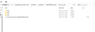
请问您使用的是哪个例程?能否给出路径?我找一下板子来测试一下,谢谢
,这个例程里用的串口0我改成了串口1
#include "driverlib.h" uint16_t i; uint8_t RXData = 0, TXData = 0; uint8_t check = 0; void main(void) { // stop watchdog WDT_A_hold(WDT_A_BASE); // LFXT Setup //Set PJ.4 and PJ.5 as Primary Module Function Input. /* * Select Port J * Set Pin 4, 5 to input Primary Module Function, LFXT. */ GPIO_setAsPeripheralModuleFunctionInputPin( GPIO_PORT_PJ, GPIO_PIN4 + GPIO_PIN5, GPIO_PRIMARY_MODULE_FUNCTION ); //Set DCO frequency to 1 MHz CS_setDCOFreq(CS_DCORSEL_0,CS_DCOFSEL_0); //Set external clock frequency to 32.768 KHz CS_setExternalClockSource(32768,0); //Set ACLK=LFXT CS_initClockSignal(CS_ACLK,CS_LFXTCLK_SELECT,CS_CLOCK_DIVIDER_1); //Set SMCLK = DCO with frequency divider of 1 CS_initClockSignal(CS_SMCLK,CS_DCOCLK_SELECT,CS_CLOCK_DIVIDER_1); //Set MCLK = DCO with frequency divider of 1 CS_initClockSignal(CS_MCLK,CS_DCOCLK_SELECT,CS_CLOCK_DIVIDER_1); //Start XT1 with no time out CS_turnOnLFXT(CS_LFXT_DRIVE_0); // Configure UART pins //Set P2.0 and P2.1 as Secondary Module Function Input. /* * Select Port 2d * Set Pin 0, 1 to input Secondary Module Function, (UCA0TXD/UCA0SIMO, UCA0RXD/UCA0SOMI). */ GPIO_setAsPeripheralModuleFunctionInputPin( GPIO_PORT_P3, GPIO_PIN4 + GPIO_PIN5, GPIO_PRIMARY_MODULE_FUNCTION ); /* * Disable the GPIO power-on default high-impedance mode to activate * previously configured port settings */ PMM_unlockLPM5(); // Configure UART EUSCI_A_UART_initParam param = {0}; param.selectClockSource = EUSCI_A_UART_CLOCKSOURCE_ACLK; param.clockPrescalar = 3; param.firstModReg = 0; param.secondModReg = 92; param.parity = EUSCI_A_UART_NO_PARITY; param.msborLsbFirst = EUSCI_A_UART_LSB_FIRST; param.numberofStopBits = EUSCI_A_UART_ONE_STOP_BIT; param.uartMode = EUSCI_A_UART_MODE; param.overSampling = EUSCI_A_UART_LOW_FREQUENCY_BAUDRATE_GENERATION; if (STATUS_FAIL == EUSCI_A_UART_init(EUSCI_A1_BASE, ¶m)) { return; } EUSCI_A_UART_enable(EUSCI_A1_BASE); EUSCI_A_UART_clearInterrupt(EUSCI_A1_BASE, EUSCI_A_UART_RECEIVE_INTERRUPT); // Enable USCI_A0 RX interrupt EUSCI_A_UART_enableInterrupt(EUSCI_A1_BASE, EUSCI_A_UART_RECEIVE_INTERRUPT); // Enable interrupt __enable_interrupt(); while (1) { //TXData = RXData; // Increment TX data // Load data onto buffer // EUSCI_A_UART_transmitData(EUSCI_A1_BASE, // TXData); /* while(check != 1); check = 0;*/ } } uint8_t buff[50]; #if defined(__TI_COMPILER_VERSION__) || defined(__IAR_SYSTEMS_ICC__) #pragma vector=USCI_A1_VECTOR __interrupt #elif defined(__GNUC__) __attribute__((interrupt(USCI_A1_VECTOR))) #endif void USCI_A1_ISR(void) { switch(__even_in_range(UCA1IV,USCI_UART_UCTXCPTIFG)) { case USCI_NONE: break; case USCI_UART_UCRXIFG: buff[RXData++] = EUSCI_A_UART_receiveData(EUSCI_A1_BASE); /* if(!(RXData == TXData)) // Check value { while(1); } check =1;*/ break; case USCI_UART_UCTXIFG: break; case USCI_UART_UCSTTIFG: break; case USCI_UART_UCTXCPTIFG: break; } }


 ,这个例程里用的串口0我改成了串口1