This thread has been locked.

If you have a related question, please click the "Ask a related question" button in the top right corner. The newly created question will be automatically linked to this question.

msp430fe4252

Other Parts Discussed in Thread: MSP430F427

在 2号和3号管脚接了一个传感器,如何使用I+,I-进行测量 ,如何配置

  • 楼主,

      你好,I+和I-接的就是内部的SD16 ADC的差分输入,就跟平时使用SD16 ADC一样使用,范例代码可以参考430ware里面的代码。


  • SD16CTL = SD16REFON+SD16SSEL0; // 1.2V ref, SMCLK

    for (i = 0; i < 10000; i++); // Delay

    /////////////////

    // SD16CCTL0 |= SD16GRP + SD16OSR_256 + SD16IE ;//控制寄存器0 组 连续模式
    // SD16CCTL0 |= SD16SC;//开始转换信号
    //SD16INCTL0 |= SD16INCH0 + SD16GAIN_1 + SD16INTDLY_0 ;//输入控制器0 选择输入通道0
    //SD16CCTL0 |= SD16SC;

    SD16INCTL1 = SD16INCH_0;
    SD16CCTL1|= SD16SNGL +SD16IE;
    SD16CCTL1 |= SD16SC;

    我是这么配置的,传感器有信号时,SD16MEM0 SD16MEM1 得到的值不变,没有信号的时候也是一样的,我是单步运行的,请帮我看看是我的设置出错了吗

  • 楼主,

          请参考下面的代码,这是操作SD16的范例代码,连续ADC转换,而且你好像只使用了一个SD16吧,

              MSP430F427
    //             -----------------
    //         /|\|              XIN|-
    //          | |                 | 32kHz
    //          --|RST          XOUT|-
    //            |                 |
    //    Vin+ -->|A2.0+            |
    //    Vin- -->|A2.0-            |
    //            |                 |
    //            |            VREF |---+
    //            |                 |   |
    //            |                 |  -+- 100nF
    //            |                 |  -+-
    //            |                 |   |
    //            |            AVss |---+
    //            |                 |
    //
    //  H. Grewal
    //  Texas Instruments Inc.
    //  Feb 2005
    //  Built with CCE Version: 3.2.0 and IAR Embedded Workbench Version: 3.21A
    //*****************************************************************************
    #include <msp430.h>


    #define   Num_of_Results   8

    /* Arrays to store SD16 conversion results */
    /* NOTE: arrays need to be global to       */
    /*       prevent removal by compiler       */
    static unsigned int results[Num_of_Results];

    int main(void)
    {
      volatile unsigned int i;                  // Use volatile to prevent removal
                                                // by compiler optimization

      WDTCTL = WDTPW + WDTHOLD;                 // Stop WDT
      FLL_CTL0 |= XCAP14PF;                     // Configure load caps
      for (i = 0; i < 10000; i++);              // Delay for 32 kHz crystal to
                                                // stabilize

      SD16CTL = SD16REFON+SD16SSEL0;            // 1.2V ref, SMCLK
      SD16INCTL2 |= SD16INTDLY0;                // Interrupt on 3rd sample
      SD16CCTL2 |= SD16IE ;                     // Enable interrupt
      for (i = 0; i < 0x3600; i++);             // Delay for 1.2V ref startup

      _EINT();                                  // Enable general interrupts

      SD16CCTL2 |= SD16SC;                      // Set bit to start conversion
      _BIS_SR(LPM0_bits);                       // Enter LPM0

    }

    #pragma vector=SD16_VECTOR
    __interrupt void SD16ISR(void)
    {
      static unsigned int index = 0;

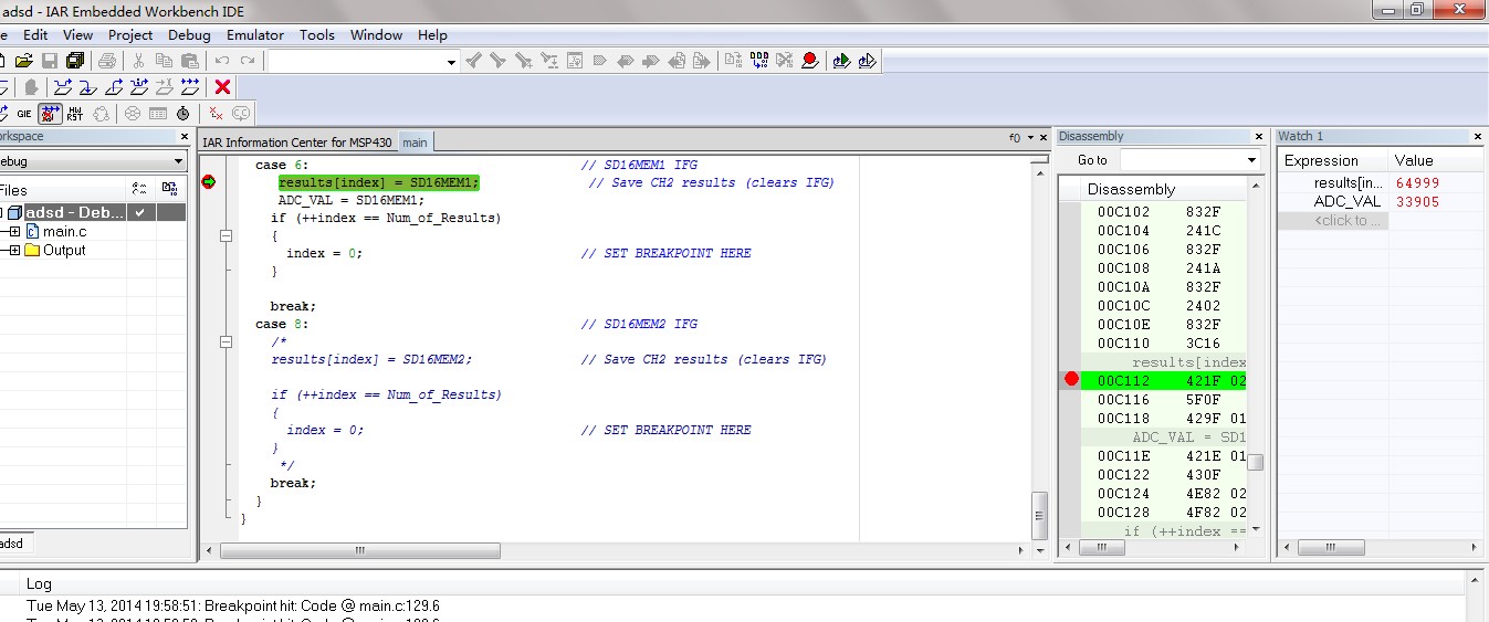
      switch (SD16IV)
      {
      case 2:                                   // SD16MEM Overflow
        break;
      case 4:                                   // SD16MEM0 IFG
        break;
      case 6:                                   // SD16MEM1 IFG
        break;
      case 8:                                   // SD16MEM2 IFG
        results[index] = SD16MEM2;              // Save CH2 results (clears IFG)

        if (++index == Num_of_Results)
        {
          index = 0;                            // SET BREAKPOINT HERE
        }

        break;
      }
    }

  • step by step 你好!

    我用的这个芯片 引脚功能 如上图,只有一个V-   V+通道和一个I+  I-通道,现在对I+ I-这个通道的操作不很理解,我也用例程改过,我之前发的就是用例程改的

  • 你好,

        I+和I-应该对应到的是SD16的通道0,所以配置的时候应该配置通道0对应的寄存器,其他的应该没有什么问题,就照的范例代码改就可以了。

  • step by step  你好!我之前用官方的例程改了,单步运行的时候 V1+ V1- 

    测得的值如图显示,很不稳定,在有稳定的电压测量的时候的值不是一个稳定的值,在一会是 0 一会是32756 一会是65535,没有电压源测量的时候也是一样的


  • 楼主,

       你用的哪个参考电压源?

  • step by step  你好 ,使用的是内部的参考电压 1.2V

  • 楼主,

        如果方便的话能不能把你的代码发出来?

  • 你好,

    你前端的传感器是用的什么传感器?

    和MCU的连接是怎么样子的,可以把这一块的电路贴出来吗?

    另外,你PCB的走线的线路图可以也一起贴出来吗?

  • step by step  你好!

    // MSP430F427
    // -----------------
    // /|\| XIN|-
    // | | | 32kHz
    // --|RST XOUT|-
    // | |
    // Vin+ -->|A2.0+ |
    // Vin- -->|A2.0- |
    // | |
    // | VREF |---+
    // | | |
    // | | -+- 100nF
    // | | -+-
    // | | |
    // | AVss |---+
    // | |
    //
    // H. Grewal
    // Texas Instruments Inc.
    // Feb 2005
    // Built with CCE Version: 3.2.0 and IAR Embedded Workbench Version: 3.21A
    //*****************************************************************************
    #include <msp430.h>
    #include "LCD.h"


    #define Num_of_Results 8


    #define BEEP(x) (x?(P1OUT&=~BIT2):(P1OUT|=BIT2))
    //Led
    #define LED_Init (P1DIR|=BIT2+BIT3+BIT5+BIT6)//初始化
    #define LED_G(x) (x?(P1OUT&=~BIT3):(P1OUT|=BIT3))//红色灯
    #define LED_B(x) (x?(P1OUT&=~BIT5):(P1OUT|=BIT5))//红色灯
    #define LED_R(x) (x?(P1OUT&=~BIT6):(P1OUT|=BIT6))//红色灯

    #define POW_R(x) (x?(P1OUT&=~BIT4):(P1OUT|=BIT4))//红色灯


    /* Arrays to store SD16 conversion results */
    /* NOTE: arrays need to be global to */
    /* prevent removal by compiler */
    static unsigned int results[Num_of_Results];
    static long ADC_VAL,results_1;


    int main(void)
    {
    volatile unsigned int i; // Use volatile to prevent removal
    // by compiler optimization

    WDTCTL = WDTPW + WDTHOLD; // Stop WDT
    FLL_CTL0 |= XCAP14PF; // Configure load caps
    for (i = 0; i < 10000; i++); // Delay for 32 kHz crystal to
    // stabilize
    LCD_Init();

    // for (i = 0; i < 0x3600; i++); // Delay for 1.2V ref startup
    P1DIR|=BIT4+BIT7;
    P1OUT&=~(BIT4);
    P1OUT|=BIT7;
    LED_Init;
    BEEP(0);
    LED_R(0);
    LED_G(0);
    LED_B(0);

    SD16CTL = SD16REFON+SD16SSEL0; // 1.2V ref, SMCLK // Enable general interrupts
    for (i = 0; i < 0x3600; i++); // Delay for 1.2V ref startup
    // SD16CTL = SD16SSEL0;
    // SD16CTL &=~(SD16REFON+SD16VMIDON) ;
    SD16INCTL0 = SD16INCH_0 + SD16GAIN_16 ;
    // SD16CCTL0|= SD16SNGL +SD16IE;
    //SD16PRE0 =8;
    SD16CCTL0 |= SD16SC;


    SD16INCTL1 |=SD16INCH_0 + SD16INTDLY0+SD16GAIN_1; // Interrupt on 3rd sample
    // SD16PRE1 =0;
    SD16CCTL1 |= SD16IE ; // Enable interrupt
    // for (i = 0; i < 0x3600; i++); // Delay for 1.2V ref startup

    // Enable general interrupts


    /*
    CCTL0 = CCIE; // CCR0 interrupt enabled
    // CCR0 = 1638; //50MSyici
    CCR0 = 1338;
    TACTL = TASSEL_1 + MC_1; // SMCLK, up mode
    */
    _EINT();

    SD16CCTL1 |= SD16SC; // Set bit to start conversion
    _BIS_SR(LPM0_bits); // Enter LPM0

    while(1)
    {

    //SD16CCTL1 |= SD16SC;
    LED_B(1);
    //BEEP(1);
    Delay_nms(500);
    LED_B(0);
    LED_G(1);
    Dis_Play_Wei(0xff,results_1/10,0xff,4);
    //BEEP(0);
    Delay_nms(500);
    LED_G(0);
    Delay_nms(500);

    }
    }

    #pragma vector=SD16_VECTOR
    __interrupt void SD16ISR(void)
    {
    static unsigned int index = 0;

    switch (SD16IV)
    {
    case 2: // SD16MEM Overflow
    break;
    case 4: // SD16MEM0 IFG
    ADC_VAL = SD16MEM0;
    break;
    case 6: // SD16MEM1 IFG
    // results[index] = SD16MEM1; // Save CH2 results (clears IFG)
    results_1 = SD16MEM1;
    ADC_VAL = SD16MEM0;
    if (++index == Num_of_Results)
    {
    index = 0; // SET BREAKPOINT HERE
    }

    break;
    case 8: // SD16MEM2 IFG
    break;
    }
    }


    // Timer A0 interrupt service routine
    #pragma vector=TIMER0_A0_VECTOR
    __interrupt void Timer_A (void)
    {
    static char time=0;

    time++;
    if(time==1)
    {
    POW_R(1);
    // SD16CCTL1 |= SD16SC;


    }
    if(time==2)
    {
    POW_R(0);
    //LED_G(0);
    }
    if(time==5)
    {
    // POW_R(1);
    // LED_R(1);
    time=0;
    }
    }


  • kqian0327 你好,  用的是压力传感器 

  • 你好,

         我手上暂时没有AFE4252的板子,你能不能帮忙先试下下面的代码,只测通道0的采样值,不管通道1,,然后分别将地和1V直接接到I+和I-上,看看结果,建议在中断中设断点来看 :

    #include <msp430.h>


    #define Num_of_Results 8

    /* Arrays to store SD16 conversion results */
    /* NOTE: arrays need to be global to */
    /* prevent removal by compiler */
    //static unsigned int results[Num_of_Results];

    static unsigned int results;

    int main(void)
    {
    volatile unsigned int i; // Use volatile to prevent removal
    // by compiler optimization

    WDTCTL = WDTPW + WDTHOLD; // Stop WDT
    FLL_CTL0 |= XCAP14PF; // Configure load caps
    for (i = 0; i < 10000; i++); // Delay for 32 kHz crystal to
    // stabilize

    SD16CTL = SD16REFON+SD16SSEL0; // 1.2V ref, SMCLK
    SD16INCTL0 |= SD16INCH_0 + SD16INTDLY0; // Interrupt on 3rd sample
    SD16CCTL0 |= SD16IE ; // Enable interrupt
    for (i = 0; i < 0x3600; i++); // Delay for 1.2V ref startup

    _EINT(); // Enable general interrupts

    SD16CCTL0 |= SD16SC; // Set bit to start conversion
    _BIS_SR(LPM0_bits); // Enter LPM0

    }

    #pragma vector=SD16_VECTOR
    __interrupt void SD16ISR(void)
    {
    static unsigned int index = 0;

    switch (SD16IV)
    {
    case 2: // SD16MEM Overflow
    break;
    case 4: // SD16MEM0 IFG

    results= SD16MEM0; // Save CH0 results (clears IFG),set break point here

    break;
    case 6: // SD16MEM1 IFG
    break;
    case 8: // SD16MEM2 IFG

    break;
    }
    }

  • 你好。假如我现在要使用外部的电压参考源的话  SD16CTL &=~(SD16REFON+SD16VMIDON)  ;  要写这句话的把

  • step by step  你好!

     单步运行的时候 测出来的值 还是会乱跳

  • 你好,
    不好意思,回复有点晚.如果使用外部参考只要设置好MCTLx寄存器的SREFx位就可以了.
    关于单步运行在跳的问题,请问你的测试源是一个稳定的直流电源吗?我有时间会找个4系列的测试一下.

  • step by step 你好 ,现在我用外部的参考电压 测量稳定的直流电压  190MV   SD16GAIN_4 

    程序如下

    #ifndef __ADC__H__
    #define __ADC__H__
    #include <msp430.h>
    long int ADC_Sum_1[3];
    int ADC_Result_1[3];

    void SD16_Test(void)
    {
    int i;
    SD16CTL |= SD16SSEL0 + SD16DIV_1; // 1.2V ref, SMCLK
    SD16CTL &=~ (SD16REFON + SD16VMIDON);//使用外部的参考电压
    for (i = 0; i < 500; i++); // Delay for 1.2V ref startup
    SD16INCTL0 |= SD16INCH_0 + SD16GAIN_4; // 增益放大4倍 惠斯通电桥 压力传感器 基本的参数为2MV/V + SD16GAIN_32
    SD16CCTL0 |= SD16DF; // Enable interrupt SD16OSR_256 +
    SD16CCTL0 |= SD16IE ; // Enable interrupt
    SD16CCTL0 |=SD16SC;
    /*
    SD16CCTL0 |= SD16GRP;//ADC0 和ADC1 为一组
    SD16INCTL1 |= SD16INCH_0; // 电源电压
    SD16CCTL1 |= SD16DF +SD16IE ; // Enable interrupt SD16OSR_128 +
    SD16CCTL1 |= SD16SC;
    */
    ADC_Sum_1[0]=0;ADC_Sum_1[1]=0;
    for (i = 0; i < 128; i++)
    {
    //while((SD16CCTL1&SD16IFG)==0);//等待完成ADC转换
    while((SD16CCTL0&SD16IFG)==0);//等待完成ADC转换
    ADC_Sum_1[0] +=(int)SD16MEM0;
    //ADC_Sum_1[1] +=(int)SD16MEM1;
    }
    //SD16CCTL1 &=~SD16SC;
    SD16CCTL0 &=~SD16SC;
    ADC_Result_1[0] =ADC_Sum_1[0]>>7;
    //ADC_Result_1[1] =ADC_Sum_1[1]>>7;
    }

    #endif

    增益放大4倍  外部的才考电压为 1.5V  应该测量的-VREF +VREF  最大可以测量 0.1875   假如我现在想采样测量0.03MV精度的电压 如何配置 ,当采样速率为SD16OSR_256 SD16 才是16位的ADC 像我这样的配置 ADC的的精度大概是多少呢