

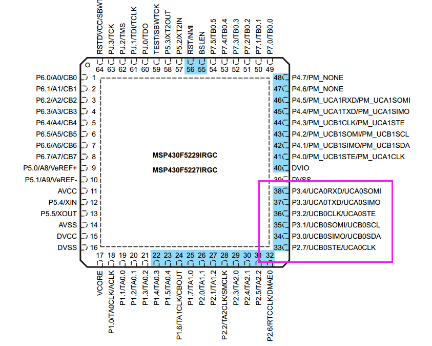
在做一个msp430F5229 +cc1120的项目,目前uca0接的是spi flash ucb0接的是cc1120的spi通讯,将两个spi都初始化了,然后往一个里面写,无法收到数据,例如写了地址读id,不返回数据,但是单个都是可以工作的。
初始化程序如下
//调试时钟配置
void halInitMCU(void)
{
WDTCTL = WDTPW + WDTHOLD; // Stop watchdog timer
//
P5SEL |= BIT2+BIT3; // Port select XT2
UCSCTL6 &= ~XT2OFF; // Enable XT2
UCSCTL3 |= SELREF_2; // FLLref = REFO
// Since LFXT1 is not used,
// sourcing FLL with LFXT1 can cause
// XT1OFFG flag to set
UCSCTL4 |= SELA_2; // //ACLK=REFO,SMCLK=DCO,MCLK=DCO
}
//初始化与CC1120连接的spi
void CC1120_SpiInit(void)
{
volatile unsigned int i;
WDTCTL = WDTPW+WDTHOLD; // Stop watchdog timer
P1DIR |= BIT7; // Set P1.7 for CSN
P2DIR |= BIT3; // Set P2.3 for slave reset
P3SEL |= BIT3+BIT4; // P3.3,4 option select
P2SEL |= BIT7; // P2.7 CLK
UCA0CTL1 |= UCSWRST; // **Put state machine in reset**
UCA0CTL0 |= UCMST+UCSYNC+UCCKPL+UCMSB; // 4-pin, 8-bit SPI master
//Clock polarity high, MSB
UCA0CTL1 |= UCSSEL_3; // SMCLK
UCA0BR0 = 0x02; // /2
UCA0BR1 = 0; //
UCA0MCTL = 0; // No modulation
UCA0CTL1 &= ~UCSWRST; // **Initialize USCI state machine**
P1OUT &= ~0x80; // p1.7 CSN low
P2OUT &= ~0x08; // p2.3 Now with SPI signals initialized,
P2OUT |= 0x08; // reset slave
//The ISR for SPI RX Date/Tx Data
for(i=50;i>0;i--); // Wait for slave to initialize
// __bis_SR_register(LPM0_bits + GIE); // CPU off, enable interrupts
}
//初始化与Flsah连接的spi
void Init_CC1120_SpiFlash()
{
P2DIR |= BIT4; //CS_N ouput
P3SEL |= BIT0+BIT1; // P3.0,1,2 option select
P3SEL |= BIT2; // P3.2 clk
UCB0CTL1 |= UCSWRST; // **Put state machine in reset**
UCB0CTL0 |= UCMST+UCSYNC+UCCKPL+UCMSB+UCMODE0; // 4-pin, 8-bit SPI slave,
// Clock polarity high, MSB
UCB0CTL1 |= UCSSEL_2; // SMCLK
// UCB0BR0 = 0x00; // /2
// UCB0BR1 = 0; //
UCB0CTL1 &= ~UCSWRST; // **Initialize USCI state machine**
}