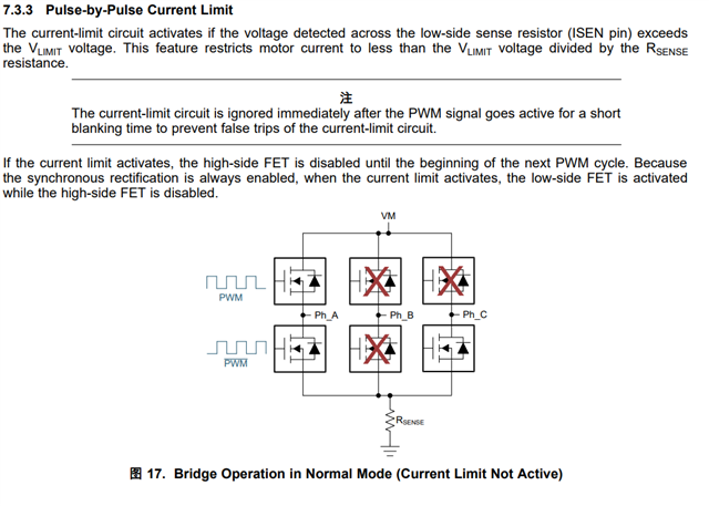
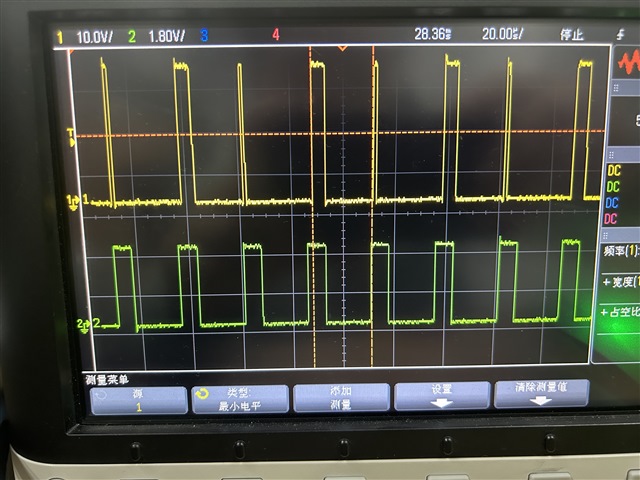
The following two signals are the control signal PWM and the A-phase voltage waveform. As shown in the figure, the yellow signal refers to the A-phase voltage waveform, which is A trapezoidal wave. The other green signal represents the PWM waveform.
I found that even if I gave the PWM_PIN of DRV8306 a 100% duty cycle PWM signal, the motor speed was still slow, about 60% of the normal state. Therefore, I collected the three-phase voltage waveform and PWM waveform of the drive circuit. On the whole, the three-phase waveform of the driving circuit presents a trapezoidal wave, which seems to be correct. But when I enlarged the waveform, I noticed something was wrong.
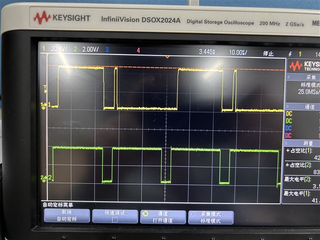
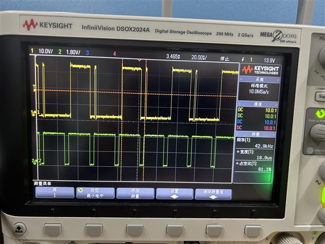
The following diagram has a PWM rating of 40KHZ and a duty cycle of about 30%, It can be seen that every two pulses can be synchronized with the PWM pulse. But in between these two pulses there is always a pulse that drops instantaneously after passing the rising edge. This led me to expect a duty cycle of 30% to control the motor speed, but in reality it was only around 15%.
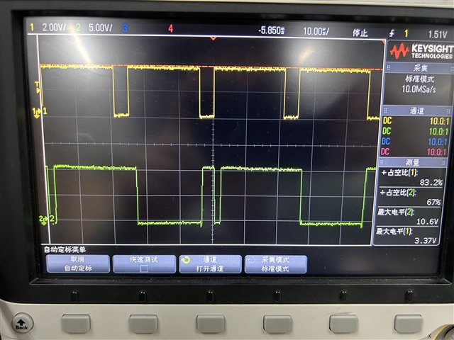
The same situation is shown in the figure below. The PWM duty cycle in the figure below is about 80%.
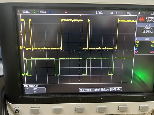
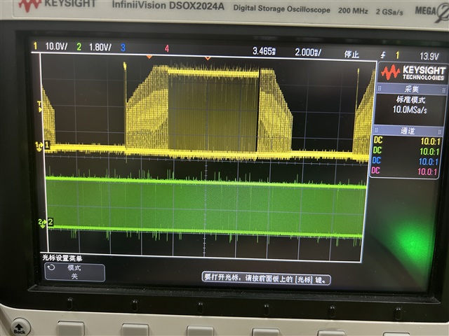
This is even more true when the PWM is 100% duty cycle. At this time, the A-phase modulation waveform of the drive circuit has completely changed into a 50% duty cycle square wave.
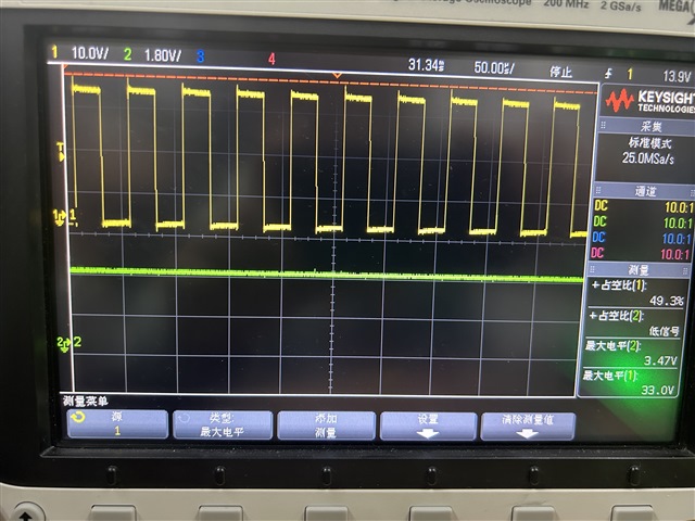
I think this is also the reason why my motor speed is slow. May I ask the experts of TI, what causes this phenomenon, and how to solve this problem.
Here is my schematic diagram of the circuit