This thread has been locked.

If you have a related question, please click the "Ask a related question" button in the top right corner. The newly created question will be automatically linked to this question.

TPS22916: TPS22916CNYFPR does not turn off

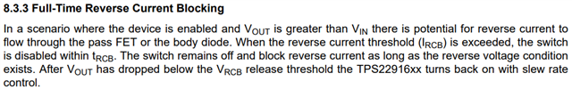
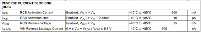
Part Number: TPS22916

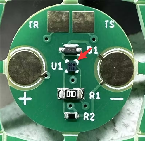
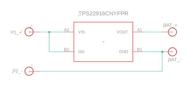
I have designed a circuit that is an interface between a charging system and a LiR1054 battery.  I chose TPS22916CNYFPR to use the RCB feature to prevent the charging terminals from being active when removed from the charging station.  This is needed to prevent possible short circuits and/or electrical leakage.  The issue that I have is that the terminals will remain powered unless I short B1 to B2 momentarily, then the terminals are isolated as needed.  I've attached a schematic of the circuit.  Can you see what is causing the RCB feature not to work.  Thanks.Screenshot 2026-02-05_22-39-56-922.png

  • In the enabled state, the IRCB threshold must be exceeded for RCB to activate and there is a detection time tRCB. What was the reverse current measured in your system? 

    The ON pin should not be connected to VOUT. It should either have its own supply or be connected to VIN. 

  • Thanks for the reply. 

    The reverse voltage is the same as the battery voltage.  About 4.2V when the battery is fully charged.  I can put a standard LED across P1_+ and P2_- and it lights up.  If I use a multimeter to measure the amps, the switch immediately shuts down and the pads are isolated.   Shorting the pads also causes the switch to shut down.

    On the schematic, P1_+ and P2_- are pogo pads that on the bottom of the board that connect to the + and - pogo pins on the charger.  The battery is wired to the BAT_+ and BAT_- pads. I've included a picture of the top of the board.  Ignore the two square pads at the top (TR and TS) they are thermistor contacts and are completely separate from the rest of the circuit.  Arrow points the to switch.  The bottom of the board contains the contacts for the pogo pads.  + and - on the top are where the battery wires are soldered to. 

  • Just tried to post a reply but nothing happened.  If this is a duplicate please ignore it.

    Hi,

    Thanks for the reply.

    The reverse voltage measured on the pogo pads (P1_+ and P2_-) is the same as the battery voltage, 4.2V on a freshly charged battery.  There is enough current coming through the pins to light a standard LED and keep it lit.  When I attempt to measure amps using a multimeter, the switch immediately shuts off all current.

    The pogo pads P1_+ and P2_- are on the bottom side of the circuit board and interact with the pogo pins on the charger.  These are the pads that need to be isolated when off of the charger.  The BAT_+ and BAT_- pads are where the battery is connected by wires.  I've included a picture of the top of the circuit board.  Ignore the TR and TS pads as they are a completely different circuit used for the battery thermistor and do not connect or interact with any other portion of the circuit, they are only connected to 2 pogo pads on the bottom side of the board that the charger uses to sense temperature.  The Red arrow shows the location of the switch.

    board top

  • The RCB activation current only applies to the device when it is enabled. RCB is always activated when the device is disabled, regardless of current through the device or even if VIN=0V.

    "The reverse voltage measured on the pogo pads (P1_+ and P2_-) is the same as the battery voltage, 4.2V on a freshly charged battery. " - So, how much voltage is applied to VIN? To reach the on-state RCB threshold, the output voltage potential needs to be greater than the input for current to flow in the reverse direction. So, I am confused by the above statement because you said the voltages are the same. However, then you state "When I attempt to measure amps using a multimeter, the switch immediately shuts off all current." Based on this observation, it seems that reverse protection is working. I'm not sure I understand what the issue is. 

  • VIN is connected to the battery through the charger.  If charging is active, then it will be > then the batteries charge.  I will admit I hadn't attempted to measure that value, but will do that tomorrow.  Voltages on P1_+ and P2_-, when the device is off the charger, measures the same voltage as is measured across the battery + and - terminals.  If I put a standard LED across P1_+ and P2_- it will still light.  I am also confused that I can measure the voltage with the same multimeter, but measuring amps somehow shuts it down.  The only thing I can think of is that the multimeter is somehow activating the reverse current protection on the chip.

    Forgive me, but I'm a little confused regarding this statement "The RCB activation current only applies to the device when it is enabled. RCB is always activated when the device is disabled,...". 

    The charger has 2 pogo pins going to the device, + and -.  These are connected to P1_+ and P2_- when on the charger.  In order to completely isolate P1_+ and P2_- when the device is off the charger it must have as complete an isolation of current from P1_+ and P2_- as these pogo pads will be exposed to water and possibly the occasional contact with conductive surfaces, and shorts/leakages through them are unacceptable for it's use. 

    If I remove everything but the essentials and route the circuit like this, would the RCB kick in and isolate P1_+ and P2_- when off the charger?

  • So, when the switch is on when ON = high, for reverse current protection to engage, the reverse current must exceed the IRCB activation current. When the switch is off, when ON = low, reverse protection is already active so that IRCB threshold does not need to be met. 

    Yes, in the new schematic, you should be able to see RCB activate. However, the output voltage potential must be greater than the input without exceeding the absolute maximum ratings. Again, the response mechanism is different as described above for the enabled versus disabled states.