

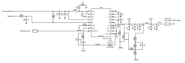
Below is the schematic that used TPS61378-Q1 as the regulator to output 5V. The input voltage is 3.3V and use an external MOSFET to switch on or off this power input.
The regulator cannot start up even with light load(0.1A). Please see the waveforms showed below. The first one is the startup waveform with no load and the second one is the startup waveform with light load(0.1A).
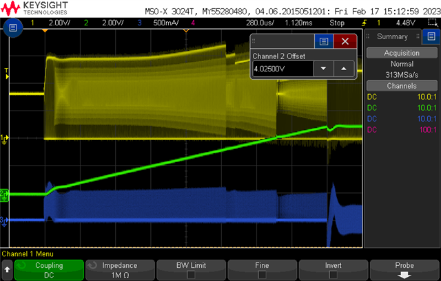
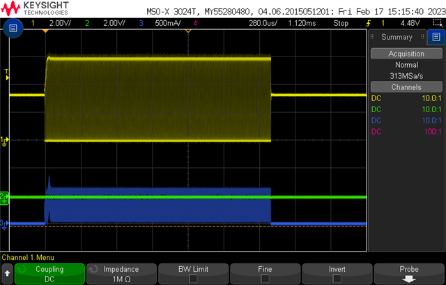
CH1-SW
CH2-VO
CH3-Inductor current
If the OUT pin is connected to the VO pin and remove C4802(2U2) on OUT pin, the regulator can start up with 0.57A load current.
I find that there is a MOSFET between the HS FET and load to cut off the path between input side and output side during shutdown.
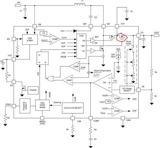
Why this MOSFET would prevent the regulator start up with light load. It seems that if the regulator is enabled but FB voltage is below 0.1V for some milliseconds, then the regulator will shut down, after that the regulator will try again.
