Other Parts Discussed in Thread: LM2611
电路图:(C1为10uF/35V的钽电容,Cout暂时没接)
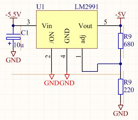
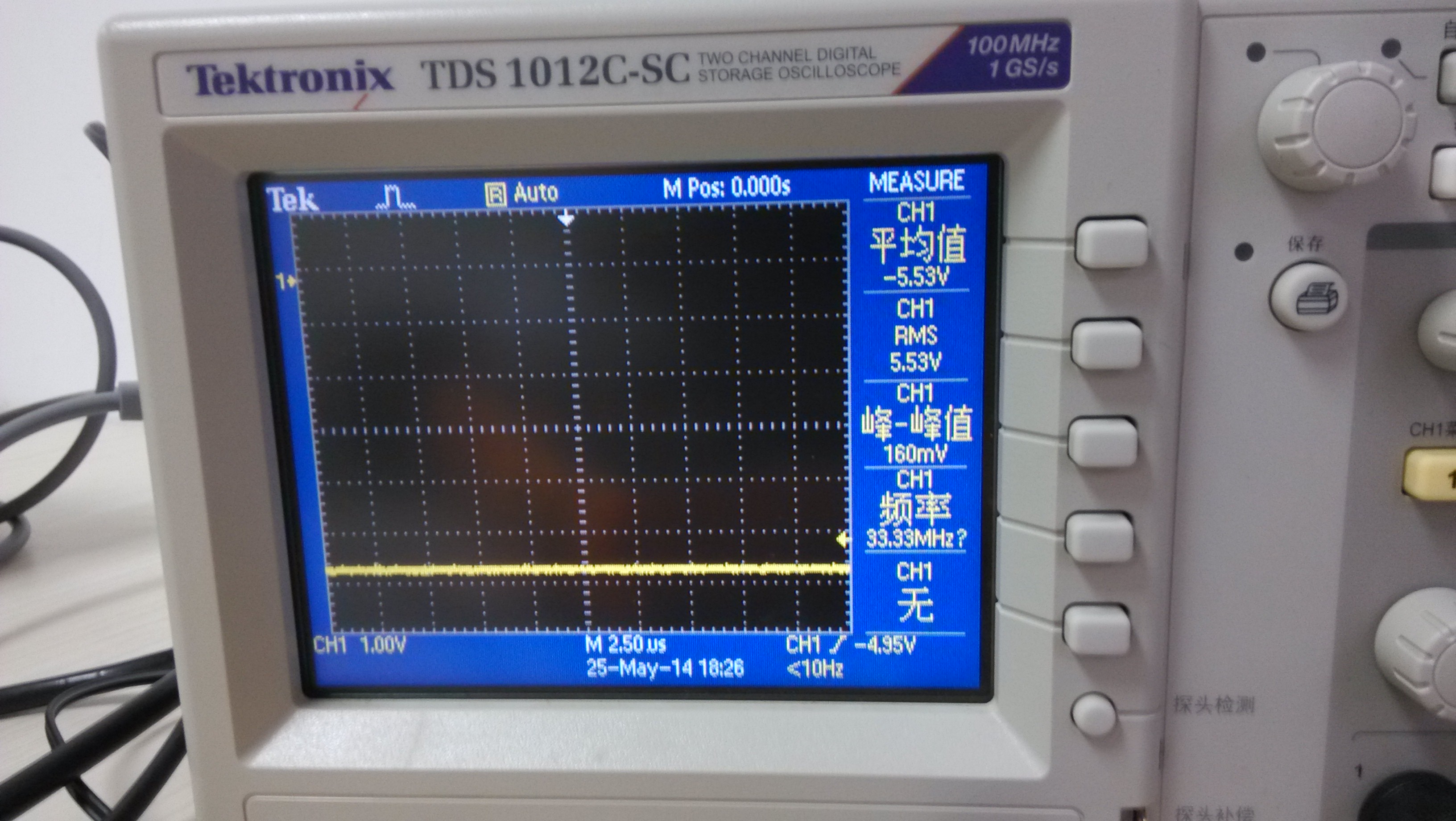
输入:-5.5V直流(由LM2611供给,已由两个220uF钽电容滤波)
输出:预计为-5V,但是空载为下面的波形(平均值为-4.92V,但是有个1.24Vpp,335kHz的分量)
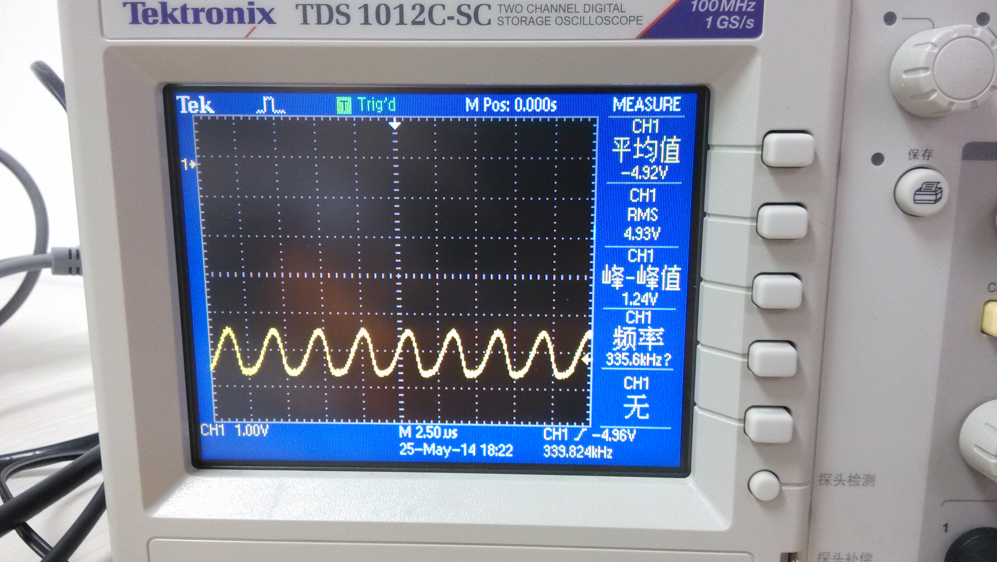
这个正常吗?即使没接输出滤波电容也不应该有这么大的一个交流分量啊~~
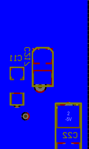
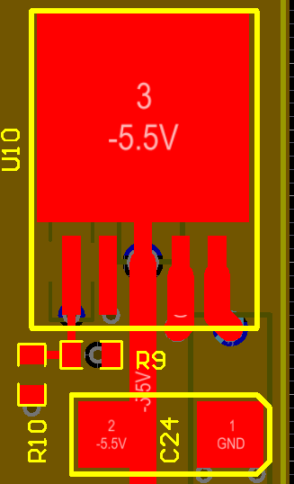
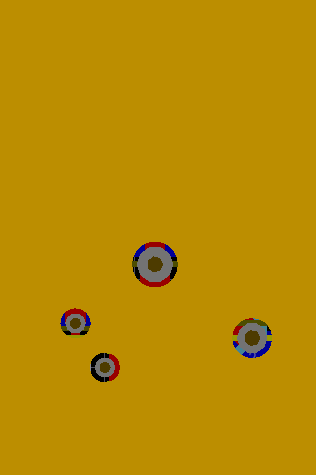
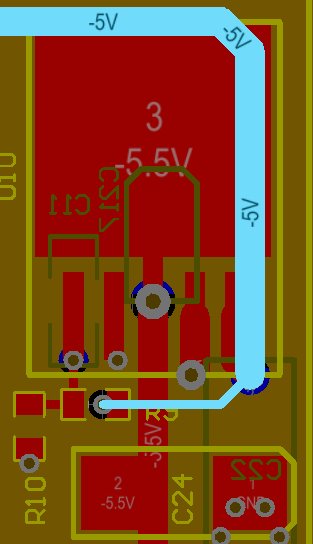
附PCB:
1.Top Layer
2.MidLayer1
3.MidLayer2
4.BottomLayer