你好!
在手册上我看到,负值是按二进制补码的方式写入,也就是我OCD3写-1000,我需要写入的二进制补码为0xFC18。同时我的电流报告单位为10mA,但是当我的放电电流大于10A的时候,OCD3并没有故障,请问一下,是我的写入方式不对,还是其它原因,谢谢。
This thread has been locked.
If you have a related question, please click the "Ask a related question" button in the top right corner. The newly created question will be automatically linked to this question.
您好,
Was the device placed into CONFIG_UPDATE mode before writing and then returned to NORMAL mode after?
If not, please follow the steps detailed in Section 7.6: CONFIG_UPDATE Mode of the TRM to place the device into the state where you can then make changes to the data memory settings by following the steps detailed in Section 13.1: Data Memory Access.
您好, 是否放便将gg文件发过来看一下.
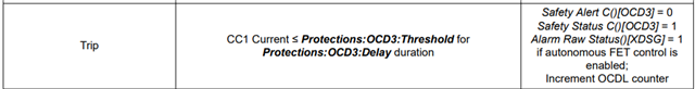
With regards to the SCD delay, it may be that the SCD current does not exceed the threshold for the whole delay time, hence why reducing the delay allows the fault to trigger. You may try observing the voltage between the SRP and SRN pins on a scope and providing a waveform capture for me to check along with the config file.
ConfigData1.Power_ConfigL = Power_Cfg; //0x0054 ConfigData1.Power_ConfigH = Power_Cfg >> 8; ConfigData1.Comm_Type = COMM_TYPE; //not use ConfigData1.REG12_Config = REG12_CFG; //0xDD ConfigData1.REG0_Config = REG0_CFG; //0x01 ConfigData1.HWD_REG_OPTION = HWDREGOPTION; //0x00 ConfigData3.En_ProtA = EN_PRTA; //use all ConfigData3.En_ProtB = EN_PRTB; //use all ConfigData3.En_ProtC = EN_PRTC; //use all ConfigData3.Prot_CfgL = PRT_CFG; //0x0000 ConfigData3.Prot_CfgH = PRT_CFG >> 8; ConfigData2.Vcell_ModeL = gBq72Connect[0]; //0xFFFF ConfigData2.Vcell_ModeH = gBq72Connect[0] >> 8; ConfigData2.DA_Cfg = DA_CFG; //0x0A ConfigData2.CFETOFF_Pin_cfg = CFETOFF_cfg; //0x02 ConfigData2.DFETOFF_Pin_cfg = DFETOFF_cfg; ConfigData2.TS1_cfg =TS1_CFG; //0x07 ConfigData2.TS2_cfg =TS2_CFG; //0x00 //TS2 use shutD ConfigData2.TS3_cfg =TS3_CFG; //0x00 ConfigData2.HDQ_Pin_Cfg = HDQ_CFG; //0x00 ConfigData2.DCHG_pin_Cfg = DCHG_CFG; //0x00 ConfigData2.DDHG_pin_Cfg = DDSG_CFG; //0x00 ConfigData4.CHGFET_ProtA = EN_CHGFET_PRTA; //0x98 ConfigData4.CHGFET_ProtB = EN_CHGFET_PRTB; //0xD5 ConfigData4.CHGFET_ProtC = EN_CHGFET_PRTC; //0x54 ConfigData5.DSGFET_ProtA = EN_DSGFET_PRTA; //0xE4 ConfigData5.DSGFET_ProtB = EN_DSGFET_PRTB; //0xE6 ConfigData5.DSGFET_ProtC = EN_DSGFET_PRTC; //0xE0 ConfigData7.Body_Diode_ThreshL = gBodyDiodePrt; //0x64 ConfigData7.Body_Diode_ThreshH = gBodyDiodePrt >> 8; BufSC = ((u16)gCurSCPrt * gCurSenseRes / 10); ConfigData7.SCD_Thresh = GetSubscriptU16(BufSC, SCDThreshTable, 16); //0x02 ConfigData7.SCD_Delay = (gDlySCPrt / 15) + 1; //0x190 ConfigData8.SCD_Rec_Time = gTimeRecSCDHardPrt; //0x02 BufSC = (((u16)gCurHardDOCPrt1 >> 1) * gCurSenseRes / 10); ConfigData7.OCD1_Thresh = BufSC; //0x02 ConfigData7.OCD1_Delay = ((u16)gDlyHardDOCPrt1*10 - 66) / 33; //0x12C //unit 3.3ms excursion 6.6 BufSC = ((gCurHardDOCPrt2 >> 1) * gCurSenseRes / 10); ConfigData7.OCD2_Thresh = BufSC; //0x04 ConfigData7.OCD2_Delay = (((u16)gDlycurHardDOCPrt2 * 10) - 66) / 33; //0x12C ConfigData7.OCD3_ThreshL = (gCurHardDOCPrt3 / 10); //-10000 uint 10mA //-1000 // userA 10mA ConfigData7.OCD3_ThreshH = (gCurHardDOCPrt3 / 10) >> 8; ConfigData7.OCD3_Delay = gDlycurHardDOCPrt3; //0x02