This thread has been locked.
If you have a related question, please click the "Ask a related question" button in the top right corner. The newly created question will be automatically linked to this question.
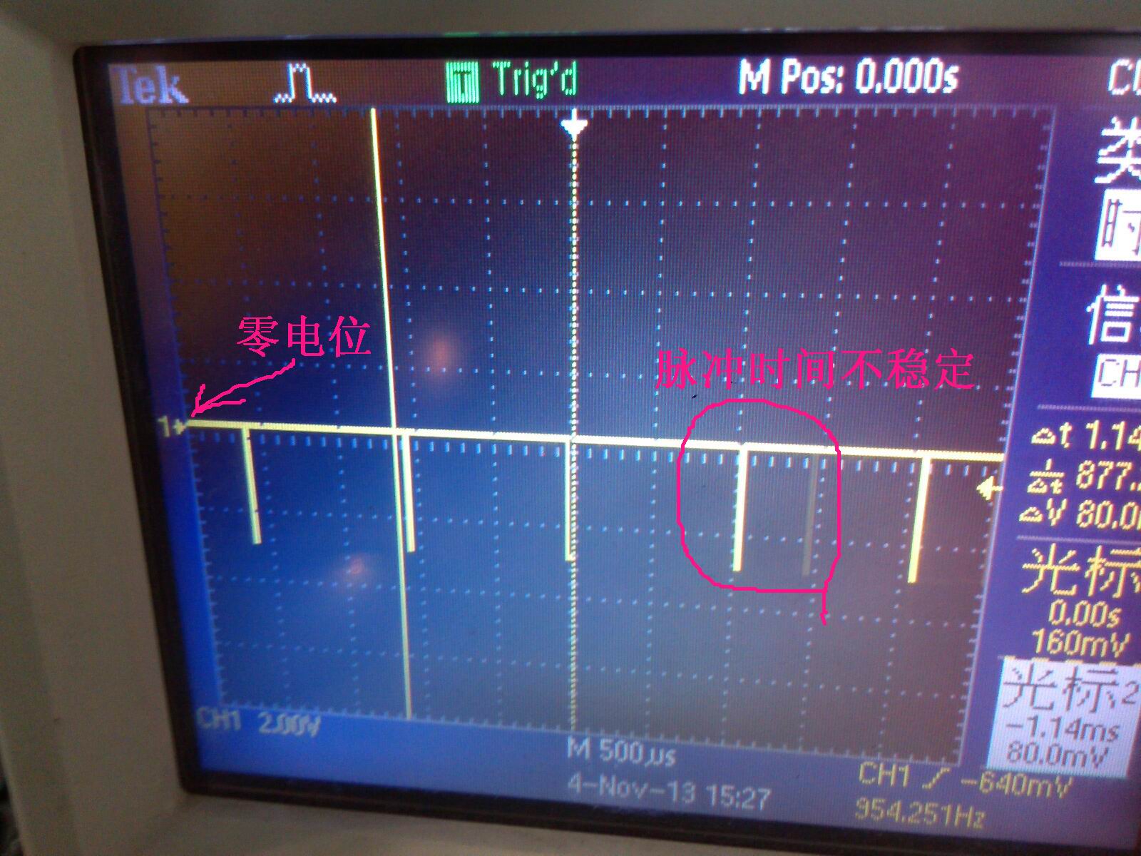
用的定时器1,端口用的P0的3和5口(通道1、3),128分频,输出比较模模式,周期1ms,输出的PWM信号中有老是一个脉冲,使得PWM信号不问题,暂时也没找到原因
SimpleBLEPeripheral基础上更改。
128分频,定时器1使用调制模式,T1CC0 = 0X00FF,通道1-3比较输出PWM脉冲。隔一段时间PWM波形里多了大概0.4mS.
void PWM_init(){//设置pwm端口为输出P0DIR|= BV(3)|BV(4)|BV(5);//设置pwm端口为外设端口,非gpioP0SEL|= BV(3)|BV(4)|BV(5);//由于uart等会占用我们当前使用的pwm端口,因此需要将uart等重映射到别的端口去。PERCFG |= 0x33; // Move USART1&2 to alternate2 location so that T1 is visibleT1CTL = 0x0e; // Div = 128, CLR, MODE = module T1CCTL1 = 0x1c; // IM = 0; CMP = Clear output on compare; Mode = CompareT1CCTL2 = 0x1c; // IM = 0; CMP = Clear output on compare; Mode = CompareT1CCTL3 = 0x1c; // IM = 0, CMP = Clear output on compare; Mode = CompareT1CNTL = 0; // Reset timer to 0;T1CNTH = 0; // Reset timer to 0;
//必须设置,否则定时器不工作T1CCTL0 = 0x4C; // IM = 1, CMP = Clear output on compare; Mode = CompareT1CC0H = 0x07; // Ticks = 375 (2.4ms)T1CC0L = 0XF8; // Ticks = 375 (2.4ms)T1CC1H = 0x03; // Ticks = 375 (1,5ms initial duty cycle)T1CC1L = 0Xc0;T1CC2H = 0x03; // Ticks = 375 (1,5ms initial duty cycle)T1CC2L = 0Xc0;T1CC3H = 0x03; // Ticks = 375 (1,5ms initial duty cycle)T1CC3L = 0Xc0; EA=1;IEN1 |= 0x02; // Enable T1 cpu interrupt}
楼主问题解决没,我也遇到了这个问题,求解答。