This thread has been locked.

If you have a related question, please click the "Ask a related question" button in the top right corner. The newly created question will be automatically linked to this question.

CC1310: CC1101 connect to CC1310 failed because of the cc1101 receive the wrong data

Part Number: CC1310
Other Parts Discussed in Thread: CC1101, , CC1350

With the CC1310 and 1310 communication data being normal, and the 1101 and 1101 communication data being normal, in non-Manchester encoding mode, the data received between CC1310 devices is the same as the data sent by the TX transmitter, ruling out the possibility of original data errors. Additionally, the frequency spectrum observed is the same, ruling out frequency offset setting issues.     Afterwards, it was found that reading the data sent by CC1101 to CC1310 through the serial port was normal, but the data sent from 1101 to 1310 did not match the original data.  

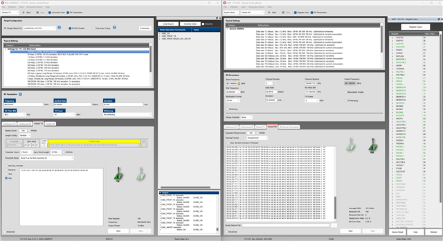
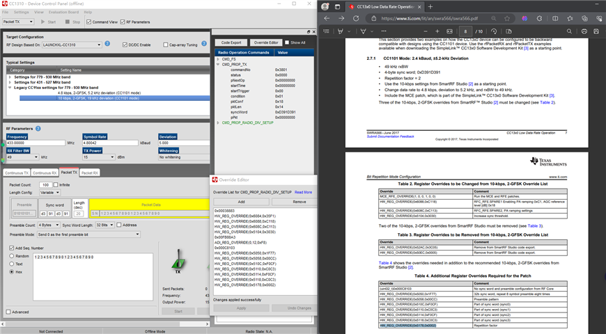
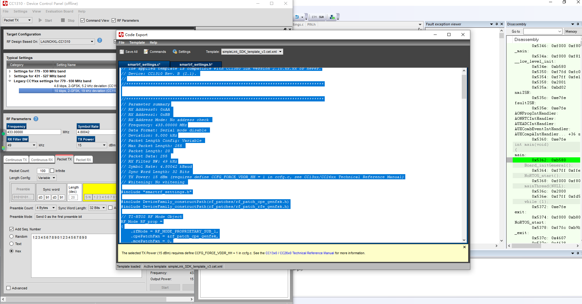
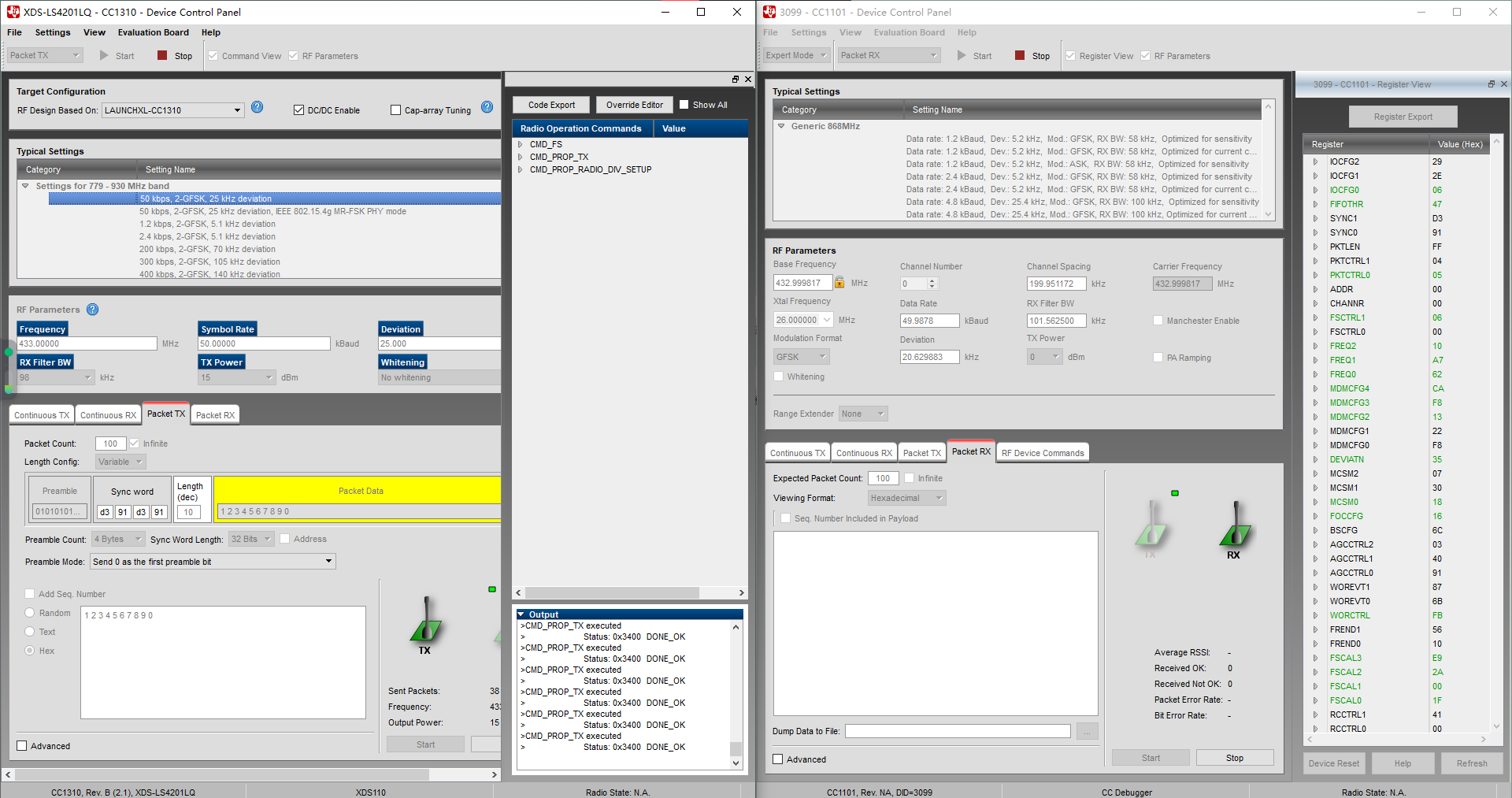
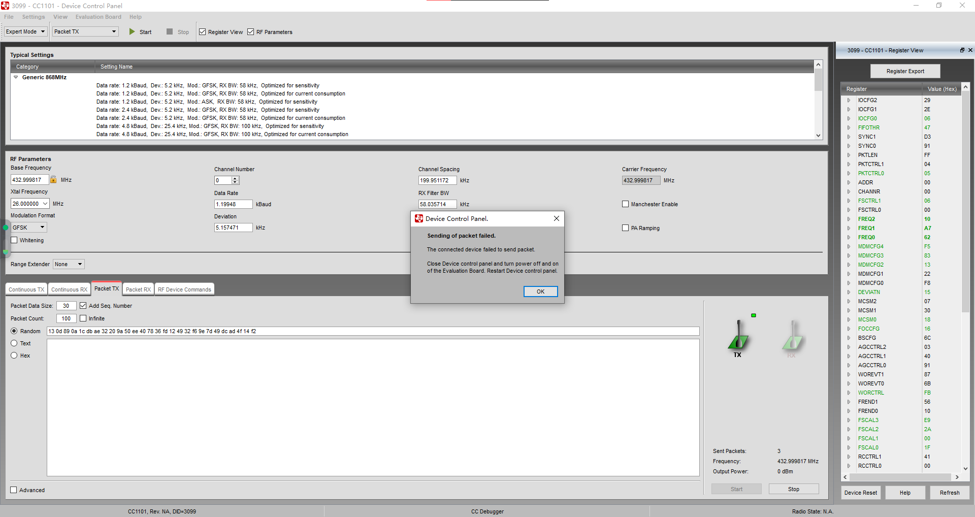
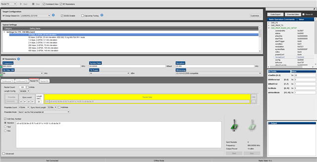
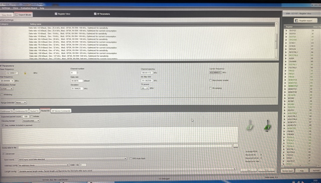
Here's the configuration:

:

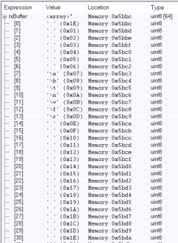
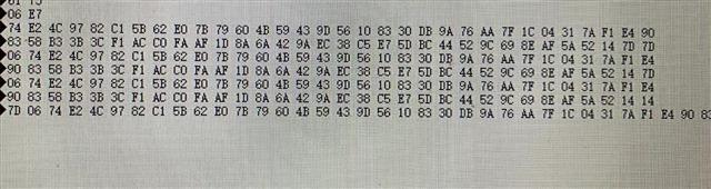
The data read from the RXfifo of 1101 contains an address, however, I did not set an address. The address read is 06, the packet length is E7, but in the 1310 program, the packet length should be 30, and the data content is also incorrect. Upon careful observation, it is found that there are three repeated segments of data, and it is unknown where they originated from.

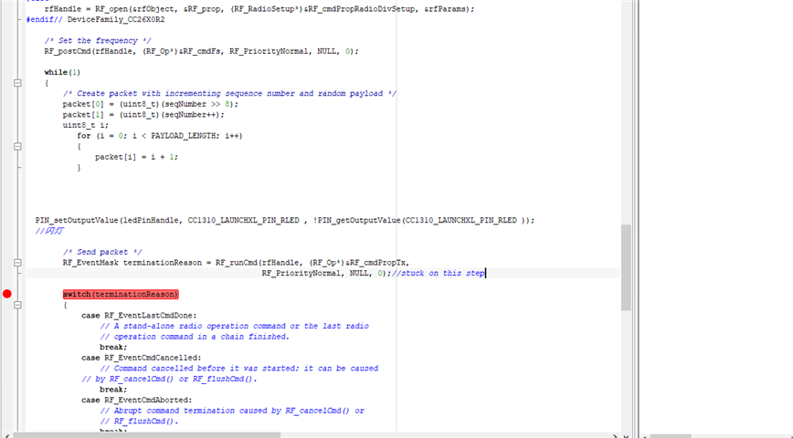
here's the expected data:

 packet[0] = PAYLOAD_LENGTH;//PAYLOAD_LENGTH=30
packet[1] = (uint8_t)(seqNumber >> 8);
packet[2] = (uint8_t)(seqNumber++);
uint8_t i;
for (i = 3; i < PAYLOAD_LENGTH +1; i++)
{
// packet[i] = rand();
packet[i] = 0x11;
}

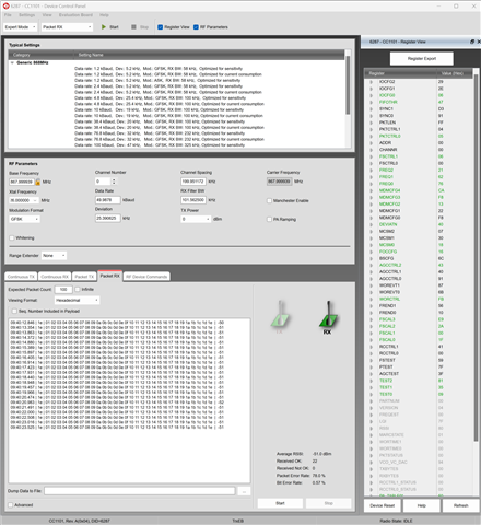
here's the cc1101 RX  code:

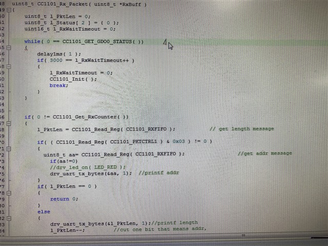
here's the receive data:

can you give me some advices for solving this problem ? thanks

  • 您好,

    https://www.ti.com/lit/an/swra566/swra566.pdf

    您可以参考一下 low datarate operation on CC1310

    另外,cc1101和cc1310之间的用的是曼彻斯特还是非曼彻斯特

  • No Manchester,did it work normaly?

  • 非曼彻斯特理论上也应该是正常工作,已经为您升级,有消息会立即通知您,谢谢

  • 久等了,以下是一个示例,你可以尝试一下

    The first method is by using SmartRF Studio:

    The register setting for both the CC1310 and the CC1101 is shown below:

    //*********************************************************************************
    // Parameter summary
    // RX Address0: 0xAA 
    // RX Address1: 0xBB 
    // RX Address Mode: No address check 
    // Frequency: 868.00000 MHz
    // Data Format: Serial mode disable 
    // Deviation: 25.000 kHz
    // Packet Length Config: Variable 
    // Max Packet Length: 255 
    // Packet Length: 30 
    // Packet Data: 255 
    // RX Filter BW: 98.0 kHz
    // Symbol Rate: 50.00000 kBaud
    // Sync Word Length: 32 Bits 
    // TX Power: 14 dBm (requires define CCFG_FORCE_VDDR_HH = 1 in ccfg.c, see CC13xx/CC26xx Technical Reference Manual)
    // Whitening: No whitening 
    
    #include "smartrf_settings.h"
    
    #include DeviceFamily_constructPath(rf_patches/rf_patch_cpe_genfsk.h)
    #include DeviceFamily_constructPath(rf_patches/rf_patch_rfe_genfsk.h)
    
    // TI-RTOS RF Mode Object
    RF_Mode RF_prop =
    {
        .rfMode = RF_MODE_PROPRIETARY_SUB_1,
        .cpePatchFxn = &rf_patch_cpe_genfsk,
        .mcePatchFxn = 0,
        .rfePatchFxn = &rf_patch_rfe_genfsk
    };
    
    
    // Overrides for CMD_PROP_RADIO_DIV_SETUP
    uint32_t pOverrides[] =
    {
        // override_use_patch_prop_genfsk.xml
        // PHY: Use MCE ROM bank 4, RFE RAM patch
        MCE_RFE_OVERRIDE(0,4,0,1,0,0),
        // override_synth_prop_863_930_div5.xml
        // Synth: Set recommended RTRIM to 7
        HW_REG_OVERRIDE(0x4038,0x0037),
        // Synth: Set Fref to 4 MHz
        (uint32_t)0x000684A3,
        // Synth: Configure fine calibration setting
        HW_REG_OVERRIDE(0x4020,0x7F00),
        // Synth: Configure fine calibration setting
        HW_REG_OVERRIDE(0x4064,0x0040),
        // Synth: Configure fine calibration setting
        (uint32_t)0xB1070503,
        // Synth: Configure fine calibration setting
        (uint32_t)0x05330523,
        // Synth: Set loop bandwidth after lock to 20 kHz
        (uint32_t)0x0A480583,
        // Synth: Set loop bandwidth after lock to 20 kHz
        (uint32_t)0x7AB80603,
        // Synth: Configure VCO LDO (in ADI1, set VCOLDOCFG=0x9F to use voltage input reference)
        ADI_REG_OVERRIDE(1,4,0x9F),
        // Synth: Configure synth LDO (in ADI1, set SLDOCTL0.COMP_CAP=1)
        ADI_HALFREG_OVERRIDE(1,7,0x4,0x4),
        // Synth: Use 24 MHz XOSC as synth clock, enable extra PLL filtering
        (uint32_t)0x02010403,
        // Synth: Configure extra PLL filtering
        (uint32_t)0x00108463,
        // Synth: Increase synth programming timeout (0x04B0 RAT ticks = 300 us)
        (uint32_t)0x04B00243,
        // override_phy_rx_aaf_bw_0xd.xml
        // Rx: Set anti-aliasing filter bandwidth to 0xD (in ADI0, set IFAMPCTL3[7:4]=0xD)
        ADI_HALFREG_OVERRIDE(0,61,0xF,0xD),
        // override_phy_gfsk_rx.xml
        // Rx: Set LNA bias current trim offset to 3
        (uint32_t)0x00038883,
        // Rx: Freeze RSSI on sync found event
        HW_REG_OVERRIDE(0x6084,0x35F1),
        // override_phy_gfsk_pa_ramp_agc_reflevel_0x1a.xml
        // Tx: Configure PA ramping setting (0x41). Rx: Set AGC reference level to 0x1A.
        HW_REG_OVERRIDE(0x6088,0x411A),
        // Tx: Configure PA ramping setting
        HW_REG_OVERRIDE(0x608C,0x8213),
        // override_phy_rx_rssi_offset_5db.xml
        // Rx: Set RSSI offset to adjust reported RSSI by +5 dB (default: 0), trimmed for external bias and differential configuration
        (uint32_t)0x00FB88A3,
        // TX power override
        // Tx: Set PA trim to max (in ADI0, set PACTL0=0xF8)
        ADI_REG_OVERRIDE(0,12,0xF8),
        (uint32_t)0xFFFFFFFF
    };
    
    
    // CMD_PROP_RADIO_DIV_SETUP
    // Proprietary Mode Radio Setup Command for All Frequency Bands
    rfc_CMD_PROP_RADIO_DIV_SETUP_t RF_cmdPropRadioDivSetup =
    {
        .commandNo = 0x3807,
        .status = 0x0000,
        .pNextOp = 0, // INSERT APPLICABLE POINTER: (uint8_t*)&xxx
        .startTime = 0x00000000,
        .startTrigger.triggerType = 0x0,
        .startTrigger.bEnaCmd = 0x0,
        .startTrigger.triggerNo = 0x0,
        .startTrigger.pastTrig = 0x0,
        .condition.rule = 0x1,
        .condition.nSkip = 0x0,
        .modulation.modType = 0x1,
        .modulation.deviation = 0x64,
        .symbolRate.preScale = 0xF,
        .symbolRate.rateWord = 0x8000,
        .symbolRate.decimMode = 0x0,
        .rxBw = 0x24,
        .preamConf.nPreamBytes = 0x4,
        .preamConf.preamMode = 0x0,
        .formatConf.nSwBits = 0x20,
        .formatConf.bBitReversal = 0x0,
        .formatConf.bMsbFirst = 0x1,
        .formatConf.fecMode = 0x0,
        .formatConf.whitenMode = 0x0,
        .config.frontEndMode = 0x0,
        .config.biasMode = 0x1,
        .config.analogCfgMode = 0x0,
        .config.bNoFsPowerUp = 0x0,
        .txPower = 0xA73F,
        .pRegOverride = pOverrides,
        .centerFreq = 0x0364,
        .intFreq = 0x8000,
        .loDivider = 0x05
    };
    
    
    // CMD_FS
    // Frequency Synthesizer Programming Command
    rfc_CMD_FS_t RF_cmdFs =
    {
        .commandNo = 0x0803,
        .status = 0x0000,
        .pNextOp = 0, // INSERT APPLICABLE POINTER: (uint8_t*)&xxx
        .startTime = 0x00000000,
        .startTrigger.triggerType = 0x0,
        .startTrigger.bEnaCmd = 0x0,
        .startTrigger.triggerNo = 0x0,
        .startTrigger.pastTrig = 0x0,
        .condition.rule = 0x1,
        .condition.nSkip = 0x0,
        .frequency = 0x0364,
        .fractFreq = 0x0000,
        .synthConf.bTxMode = 0x0,
        .synthConf.refFreq = 0x0,
        .__dummy0 = 0x00,
        .__dummy1 = 0x00,
        .__dummy2 = 0x00,
        .__dummy3 = 0x0000
    };
    
    
    // CMD_PROP_TX
    // Proprietary Mode Transmit Command
    rfc_CMD_PROP_TX_t RF_cmdPropTx =
    {
        .commandNo = 0x3801,
        .status = 0x0000,
        .pNextOp = 0, // INSERT APPLICABLE POINTER: (uint8_t*)&xxx
        .startTime = 0x00000000,
        .startTrigger.triggerType = 0x0,
        .startTrigger.bEnaCmd = 0x0,
        .startTrigger.triggerNo = 0x0,
        .startTrigger.pastTrig = 0x0,
        .condition.rule = 0x1,
        .condition.nSkip = 0x0,
        .pktConf.bFsOff = 0x0,
        .pktConf.bUseCrc = 0x1,
        .pktConf.bVarLen = 0x1,
        .pktLen = 0x1E,
        .syncWord = 0xD391D391,
        .pPkt = 0 // INSERT APPLICABLE POINTER: (uint8_t*)&xxx
    };
    
    
    // CMD_PROP_RX
    // Proprietary Mode Receive Command
    rfc_CMD_PROP_RX_t RF_cmdPropRx =
    {
        .commandNo = 0x3802,
        .status = 0x0000,
        .pNextOp = 0, // INSERT APPLICABLE POINTER: (uint8_t*)&xxx
        .startTime = 0x00000000,
        .startTrigger.triggerType = 0x0,
        .startTrigger.bEnaCmd = 0x0,
        .startTrigger.triggerNo = 0x0,
        .startTrigger.pastTrig = 0x0,
        .condition.rule = 0x1,
        .condition.nSkip = 0x0,
        .pktConf.bFsOff = 0x0,
        .pktConf.bRepeatOk = 0x0,
        .pktConf.bRepeatNok = 0x0,
        .pktConf.bUseCrc = 0x1,
        .pktConf.bVarLen = 0x1,
        .pktConf.bChkAddress = 0x0,
        .pktConf.endType = 0x0,
        .pktConf.filterOp = 0x0,
        .rxConf.bAutoFlushIgnored = 0x0,
        .rxConf.bAutoFlushCrcErr = 0x0,
        .rxConf.bIncludeHdr = 0x1,
        .rxConf.bIncludeCrc = 0x0,
        .rxConf.bAppendRssi = 0x0,
        .rxConf.bAppendTimestamp = 0x0,
        .rxConf.bAppendStatus = 0x1,
        .syncWord = 0xD391D391,
        .maxPktLen = 0xFF,
        .address0 = 0xAA,
        .address1 = 0xBB,
        .endTrigger.triggerType = 0x1,
        .endTrigger.bEnaCmd = 0x0,
        .endTrigger.triggerNo = 0x0,
        .endTrigger.pastTrig = 0x0,
        .endTime = 0x00000000,
        .pQueue = 0, // INSERT APPLICABLE POINTER: (dataQueue_t*)&xxx
        .pOutput = 0 // INSERT APPLICABLE POINTER: (uint8_t*)&xxx
    };

    /* Address Config = No address check */
    /* Base Frequency = 867.999939 */
    /* CRC Autoflush = false */
    /* CRC Enable = true */
    /* Carrier Frequency = 867.999939 */
    /* Channel Number = 0 */
    /* Channel Spacing = 199.951172 */
    /* Data Format = Normal mode */
    /* Data Rate = 49.9878 */
    /* Deviation = 25.390625 */
    /* Device Address = 0 */
    /* Manchester Enable = false */
    /* Modulated = true */
    /* Modulation Format = GFSK */
    /* PA Ramping = false */
    /* Packet Length = 255 */
    /* Packet Length Mode = Variable packet length mode. Packet length configured by the first byte after sync word */
    /* Preamble Count = 4 */
    /* RX Filter BW = 101.562500 */
    /* Sync Word Qualifier Mode = 30/32 sync word bits detected */
    /* TX Power = 0 */
    /* Whitening = false */
    /* PA table */
    #define PA_TABLE {0x50,0x00,0x00,0x00,0x00,0x00,0x00,0x00}
    /***************************************************************
     *  SmartRF Studio(tm) Export
     *
     *  Radio register settings specifed with C-code
     *  compatible #define statements.
     *
     *  RF device: CC1101
     *
     ***************************************************************/
    
    #ifndef SMARTRF_CC1101_H
    #define SMARTRF_CC1101_H
    
    #define SMARTRF_RADIO_CC1101
    #define SMARTRF_SETTING_IOCFG0       0x06
    #define SMARTRF_SETTING_FIFOTHR      0x47
    #define SMARTRF_SETTING_PKTCTRL0     0x05
    #define SMARTRF_SETTING_FSCTRL1      0x06
    #define SMARTRF_SETTING_FREQ2        0x21
    #define SMARTRF_SETTING_FREQ1        0x62
    #define SMARTRF_SETTING_FREQ0        0x76
    #define SMARTRF_SETTING_MDMCFG4      0xCA
    #define SMARTRF_SETTING_MDMCFG3      0xF8
    #define SMARTRF_SETTING_MDMCFG2      0x13
    #define SMARTRF_SETTING_DEVIATN      0x40
    #define SMARTRF_SETTING_MCSM0        0x18
    #define SMARTRF_SETTING_FOCCFG       0x16
    #define SMARTRF_SETTING_AGCCTRL2     0x43
    #define SMARTRF_SETTING_WORCTRL      0xFB
    #define SMARTRF_SETTING_FSCAL3       0xE9
    #define SMARTRF_SETTING_FSCAL2       0x2A
    #define SMARTRF_SETTING_FSCAL1       0x00
    #define SMARTRF_SETTING_FSCAL0       0x1F
    #define SMARTRF_SETTING_TEST2        0x81
    #define SMARTRF_SETTING_TEST1        0x35
    #define SMARTRF_SETTING_TEST0        0x09
    #define SMARTRF_SETTING_LQI          0x7F
    #define SMARTRF_SETTING_RSSI         0x80
    #define SMARTRF_SETTING_MARCSTATE    0x01
    #define SMARTRF_SETTING_VCO_VC_DAC   0x94
    
    #endif

    I also took the rfPacketTX example from the 4.20 SDK and modified it with the settings shown above.

    The packet content was changed as follows:

    while(1)
    {
        /* Create packet with incrementing sequence number and random payload */
        //packet[0] = (uint8_t)(seqNumber >> 8);
        //packet[1] = (uint8_t)(seqNumber++);
        uint8_t i;
        for (i = 0; i < PAYLOAD_LENGTH; i++)
        {
            packet[i] = i + 1;
        }
    
        /* Send packet */
        RF_EventMask terminationReason = RF_runCmd(rfHandle, (RF_Op*)&RF_cmdPropTx,
                                                   RF_PriorityNormal, NULL, 0);

    Also these packets where received correctly by CC1101 and SmartRF Studio:

    I also made a small CC1101 program where I used the same settings as above, and verified that also here the packets was received correctly:

    #define ISR_ACTION_REQUIRED 1
    #define ISR_IDLE            0
    
    #define PKTLEN              30
    
    #define GPIO2               0x08
    #define GPIO0               0x80
    
    
    /*******************************************************************************
    * LOCAL VARIABLES
    */
    static uint8  packetSemaphore;
    static uint32 packetCounter = 0;
    
    
    /*******************************************************************************
    * STATIC FUNCTIONS
    */
    static void initMCU(void);
    static void registerConfig(void);
    static void runRX(void);
    static void radioRxISR(void);
    
    
    /*******************************************************************************
    *   @fn         main
    *
    *   @brief      Runs the main routine
    *
    *   @param      none
    *
    *   @return     none
    */
    void main(void) {
    
        // initialize MCU and peripherals
        initMCU();
    
        // Write radio registers
        registerConfig();
    
        // Enter runRX, never coming back
        runRX();
    }
    
    static void runRX(void) {
    
        uint8 rxBuffer[64] = {0};
        uint8 rxBytes;
        uint8 marcstate;
    
        // Connect ISR function to GPIO0
        ioPinIntRegister(IO_PIN_PORT_1, GPIO0, &radioRxISR);
    
        // Interrupt on falling edge
        ioPinIntTypeSet(IO_PIN_PORT_1, GPIO0, IO_PIN_FALLING_EDGE);
    
        // Clear ISR flag
        ioPinIntClear(IO_PIN_PORT_1, GPIO0);
    
        // Enable interrupt
        ioPinIntEnable(IO_PIN_PORT_1, GPIO0);
    
        // Update LCD
        updateLcd();
    
        // Set radio in RX
        trxSpiCmdStrobe(CC1101_SRX);
    
        // Infinite loop 
        while(TRUE) {
        
            // wait for packet received interrupt
            if(packetSemaphore == ISR_ACTION_REQUIRED) {
            
                // Read number of bytes in RX FIFO
                cc1101SpiReadReg(CC1101_RXBYTES,&rxBytes,1);
                
                // Check that we have bytes in FIFO
                if(rxBytes != 0) {
    
                    // Check for RX FIFO overflow (MSB of RXBYTES)
                    if(rxBytes & 0x80) {
    
                        // Flush RX FIFO
                        trxSpiCmdStrobe(CC1101_SFRX);
                    } else {
    
                        // Read n bytes from RX FIFO
                        cc1101SpiReadRxFifo(rxBuffer,(rxBytes));
                        
                        // Check CRC ok (CRC_OK: bit7 in second status byte)
                        // This assumes status bytes are appended in RX_FIFO
                        // (PKTCTRL1.APPEND_STATUS = 1)
                        // If CRC is disabled the CRC_OK field will read 1
                        if(rxBuffer[rxBytes - 1] & 0x80) {
    
                            // Update packet counter
                            packetCounter++;
                        }
                    }
                }
    
                // Reset packet semaphore
                packetSemaphore = ISR_IDLE;
    
                // Set radio back in RX
                trxSpiCmdStrobe(CC1101_SRX);
            }
        }
    }
    
    static void radioRxISR(void) {
    
        // Set packet semaphore
        packetSemaphore = ISR_ACTION_REQUIRED;
    
        // Clear ISR flag
        ioPinIntClear(IO_PIN_PORT_1, GPIO2);
    }

    Hope this helps.

  • 请问提供的示例对你的问题是否有帮助?目前你的问题得到解决了吗?

  • Hello, thank you for your answer, but the SmartRFstudio panel in the above example is fuzzy, which may be due to the compression of the image, I can't see clearly. Could you please provide a clearer picture?thanks.

  • 应该有更清晰一些了,你可以对照尝试一下

  • Hello, I have tried, CC1310 and CC1101 both use the 868MHZ setting of your example above, then import the corresponding register, and use CC1310 to send, found that CC1101 still can not receive data

    CC1310's code :

    void *mainThread(void *arg0)
    {
    RF_Params rfParams;
    RF_Params_init(&rfParams);

    /* Open LED pins */
    ledPinHandle = PIN_open(&ledPinState, pinTable);
    if (ledPinHandle == NULL)
    {
    while(1);

    }

    #ifdef POWER_MEASUREMENT
    #if defined(Board_CC1350_LAUNCHXL)
    /* Route out PA active pin to Board_DIO30_SWPWR */
    PINCC26XX_setMux(ledPinHandle, Board_DIO30_SWPWR, PINCC26XX_MUX_RFC_GPO1);
    #endif
    #endif

    RF_cmdPropTx.pktLen = PAYLOAD_LENGTH;
    RF_cmdPropTx.pPkt = packet;
    RF_cmdPropTx.startTrigger.triggerType = TRIG_NOW;

    /* Request access to the radio */
    #if defined(DeviceFamily_CC26X0R2)
    rfHandle = RF_open(&rfObject, &RF_prop, (RF_RadioSetup*)&RF_cmdPropRadioSetup, &rfParams);
    #else
    rfHandle = RF_open(&rfObject, &RF_prop, (RF_RadioSetup*)&RF_cmdPropRadioDivSetup, &rfParams);
    #endif// DeviceFamily_CC26X0R2

    /* Set the frequency */
    RF_postCmd(rfHandle, (RF_Op*)&RF_cmdFs, RF_PriorityNormal, NULL, 0);

    while(1)
    {
    /* Create packet with incrementing sequence number and random payload */
    packet[0] = (uint8_t)(seqNumber >> 8);
    packet[1] = (uint8_t)(seqNumber++);
    uint8_t i;
    for (i = 0; i < PAYLOAD_LENGTH; i++)
    {
    packet[i] = i + 1;

    }


    PIN_setOutputValue(ledPinHandle, CC1310_LAUNCHXL_PIN_RLED , !PIN_getOutputValue(CC1310_LAUNCHXL_PIN_RLED ));
    //reverse

    /* Send packet */
    RF_EventMask terminationReason = RF_runCmd(rfHandle, (RF_Op*)&RF_cmdPropTx,
    RF_PriorityNormal, NULL, 0);

    }

    I am quite sure that 1101 and 1101 can communicate with each other using the 1101 setting you recommended, that is, 1101 data can be received normally, and then CC1310 can be observed with normal waveform emitted on the spectrometer. Besides, I use CC1310 and CC1101 to connect to the RFstudio7 configuration panel at the same time. In addition to the frequency set to 433, other unchanged, the result is not received from 1101 data, can be observed from the continuous reception of 1101 waveform is present, but can not receive data, and then 1310 and 1101 on both sides of the burning program method, manually modify the parameter to 433MHZ can not receive data

  • The problem still hasn't been solved, I would like to ask if you can give me a routine of CC1310 transmitting and CC1101 receiving at 433MHZ, and give the RF parameter configuration of both sides, thank you

  • 好的,为您继续跟进,有消息立马通知您。

  • Also, the first use www.ti.com/.../swra566.pdf to recommend setting, manually modify parameters of backwardness stuck on runcmd function  , what reason be?

  • 您好,为了方便大家查阅,我们只讨论一个topic,衍生问题请您发新帖,谢谢配合。

  • CC1310 transmitting at 433 and CC1101 receiving:

    CC1310 Settings:

    //*********************************************************************************
    // Parameter summary
    // RX Address0: 0xAA 
    // RX Address1: 0xBB 
    // RX Address Mode: No address check 
    // Frequency: 433.00000 MHz
    // Data Format: Serial mode disable 
    // Deviation: 25.000 kHz
    // Packet Length Config: Variable 
    // Max Packet Length: 255 
    // Packet Length: 10 
    // Packet Data: 255 
    // RX Filter BW: 98.0 kHz
    // Symbol Rate: 50.00000 kBaud
    // Sync Word Length: 32 Bits 
    // TX Power: 15 dBm (requires define CCFG_FORCE_VDDR_HH = 1 in ccfg.c, see CC13xx/CC26xx Technical Reference Manual)
    // Whitening: No whitening 
    
    #include "smartrf_settings.h"
    
    #include DeviceFamily_constructPath(rf_patches/rf_patch_cpe_genfsk.h)
    #include DeviceFamily_constructPath(rf_patches/rf_patch_rfe_genfsk.h)
    
    // TI-RTOS RF Mode Object
    RF_Mode RF_prop =
    {
        .rfMode = RF_MODE_PROPRIETARY_SUB_1,
        .cpePatchFxn = &rf_patch_cpe_genfsk,
        .mcePatchFxn = 0,
        .rfePatchFxn = &rf_patch_rfe_genfsk
    };
    
    
    // Overrides for CMD_PROP_RADIO_DIV_SETUP
    uint32_t pOverrides[] =
    {
        // override_use_patch_prop_genfsk.xml
        // PHY: Use MCE ROM bank 4, RFE RAM patch
        MCE_RFE_OVERRIDE(0,4,0,1,0,0),
        // override_synth_prop_863_930_div5.xml
        // Synth: Set recommended RTRIM to 7
        HW_REG_OVERRIDE(0x4038,0x0037),
        // Synth: Set Fref to 4 MHz
        (uint32_t)0x000684A3,
        // Synth: Configure fine calibration setting
        HW_REG_OVERRIDE(0x4020,0x7F00),
        // Synth: Configure fine calibration setting
        HW_REG_OVERRIDE(0x4064,0x0040),
        // Synth: Configure fine calibration setting
        (uint32_t)0xB1070503,
        // Synth: Configure fine calibration setting
        (uint32_t)0x05330523,
        // Synth: Set loop bandwidth after lock to 20 kHz
        (uint32_t)0x0A480583,
        // Synth: Set loop bandwidth after lock to 20 kHz
        (uint32_t)0x7AB80603,
        // Synth: Configure VCO LDO (in ADI1, set VCOLDOCFG=0x9F to use voltage input reference)
        ADI_REG_OVERRIDE(1,4,0x9F),
        // Synth: Configure synth LDO (in ADI1, set SLDOCTL0.COMP_CAP=1)
        ADI_HALFREG_OVERRIDE(1,7,0x4,0x4),
        // Synth: Use 24 MHz XOSC as synth clock, enable extra PLL filtering
        (uint32_t)0x02010403,
        // Synth: Configure extra PLL filtering
        (uint32_t)0x00108463,
        // Synth: Increase synth programming timeout (0x04B0 RAT ticks = 300 us)
        (uint32_t)0x04B00243,
        // override_phy_rx_aaf_bw_0xd.xml
        // Rx: Set anti-aliasing filter bandwidth to 0xD (in ADI0, set IFAMPCTL3[7:4]=0xD)
        ADI_HALFREG_OVERRIDE(0,61,0xF,0xD),
        // override_phy_gfsk_rx.xml
        // Rx: Set LNA bias current trim offset to 3
        (uint32_t)0x00038883,
        // Rx: Freeze RSSI on sync found event
        HW_REG_OVERRIDE(0x6084,0x35F1),
        // override_phy_gfsk_pa_ramp_agc_reflevel_0x1a.xml
        // Tx: Configure PA ramping setting (0x41). Rx: Set AGC reference level to 0x1A.
        HW_REG_OVERRIDE(0x6088,0x411A),
        // Tx: Configure PA ramping setting
        HW_REG_OVERRIDE(0x608C,0x8213),
        // override_phy_rx_rssi_offset_5db.xml
        // Rx: Set RSSI offset to adjust reported RSSI by +5 dB (default: 0), trimmed for external bias and differential configuration
        (uint32_t)0x00FB88A3,
        // TX power override
        // Tx: Set PA trim to max (in ADI0, set PACTL0=0xF8)
        ADI_REG_OVERRIDE(0,12,0xF8),
        (uint32_t)0xFFFFFFFF
    };
    
    
    // CMD_PROP_RADIO_DIV_SETUP
    // Proprietary Mode Radio Setup Command for All Frequency Bands
    rfc_CMD_PROP_RADIO_DIV_SETUP_t RF_cmdPropRadioDivSetup =
    {
        .commandNo = 0x3807,
        .status = 0x0000,
        .pNextOp = 0, // INSERT APPLICABLE POINTER: (uint8_t*)&xxx
        .startTime = 0x00000000,
        .startTrigger.triggerType = 0x0,
        .startTrigger.bEnaCmd = 0x0,
        .startTrigger.triggerNo = 0x0,
        .startTrigger.pastTrig = 0x0,
        .condition.rule = 0x1,
        .condition.nSkip = 0x0,
        .modulation.modType = 0x1,
        .modulation.deviation = 0x64,
        .symbolRate.preScale = 0xF,
        .symbolRate.rateWord = 0x8000,
        .symbolRate.decimMode = 0x0,
        .rxBw = 0x24,
        .preamConf.nPreamBytes = 0x4,
        .preamConf.preamMode = 0x0,
        .formatConf.nSwBits = 0x20,
        .formatConf.bBitReversal = 0x0,
        .formatConf.bMsbFirst = 0x1,
        .formatConf.fecMode = 0x0,
        .formatConf.whitenMode = 0x0,
        .config.frontEndMode = 0x0,
        .config.biasMode = 0x1,
        .config.analogCfgMode = 0x0,
        .config.bNoFsPowerUp = 0x0,
        .txPower = 0x913F,
        .pRegOverride = pOverrides,
        .centerFreq = 0x01B1,
        .intFreq = 0x8000,
        .loDivider = 0x0A
    };
    
    
    // CMD_FS
    // Frequency Synthesizer Programming Command
    rfc_CMD_FS_t RF_cmdFs =
    {
        .commandNo = 0x0803,
        .status = 0x0000,
        .pNextOp = 0, // INSERT APPLICABLE POINTER: (uint8_t*)&xxx
        .startTime = 0x00000000,
        .startTrigger.triggerType = 0x0,
        .startTrigger.bEnaCmd = 0x0,
        .startTrigger.triggerNo = 0x0,
        .startTrigger.pastTrig = 0x0,
        .condition.rule = 0x1,
        .condition.nSkip = 0x0,
        .frequency = 0x01B1,
        .fractFreq = 0x0000,
        .synthConf.bTxMode = 0x0,
        .synthConf.refFreq = 0x0,
        .__dummy0 = 0x00,
        .__dummy1 = 0x00,
        .__dummy2 = 0x00,
        .__dummy3 = 0x0000
    };
    
    
    // CMD_PROP_TX
    // Proprietary Mode Transmit Command
    rfc_CMD_PROP_TX_t RF_cmdPropTx =
    {
        .commandNo = 0x3801,
        .status = 0x0000,
        .pNextOp = 0, // INSERT APPLICABLE POINTER: (uint8_t*)&xxx
        .startTime = 0x00000000,
        .startTrigger.triggerType = 0x0,
        .startTrigger.bEnaCmd = 0x0,
        .startTrigger.triggerNo = 0x0,
        .startTrigger.pastTrig = 0x0,
        .condition.rule = 0x1,
        .condition.nSkip = 0x0,
        .pktConf.bFsOff = 0x0,
        .pktConf.bUseCrc = 0x1,
        .pktConf.bVarLen = 0x1,
        .pktLen = 0x0A,
        .syncWord = 0xD391D391,
        .pPkt = 0 // INSERT APPLICABLE POINTER: (uint8_t*)&xxx
    };
    
    
    // CMD_PROP_RX
    // Proprietary Mode Receive Command
    rfc_CMD_PROP_RX_t RF_cmdPropRx =
    {
        .commandNo = 0x3802,
        .status = 0x0000,
        .pNextOp = 0, // INSERT APPLICABLE POINTER: (uint8_t*)&xxx
        .startTime = 0x00000000,
        .startTrigger.triggerType = 0x0,
        .startTrigger.bEnaCmd = 0x0,
        .startTrigger.triggerNo = 0x0,
        .startTrigger.pastTrig = 0x0,
        .condition.rule = 0x1,
        .condition.nSkip = 0x0,
        .pktConf.bFsOff = 0x0,
        .pktConf.bRepeatOk = 0x0,
        .pktConf.bRepeatNok = 0x0,
        .pktConf.bUseCrc = 0x1,
        .pktConf.bVarLen = 0x1,
        .pktConf.bChkAddress = 0x0,
        .pktConf.endType = 0x0,
        .pktConf.filterOp = 0x0,
        .rxConf.bAutoFlushIgnored = 0x0,
        .rxConf.bAutoFlushCrcErr = 0x0,
        .rxConf.bIncludeHdr = 0x1,
        .rxConf.bIncludeCrc = 0x0,
        .rxConf.bAppendRssi = 0x0,
        .rxConf.bAppendTimestamp = 0x0,
        .rxConf.bAppendStatus = 0x1,
        .syncWord = 0xD391D391,
        .maxPktLen = 0xFF,
        .address0 = 0xAA,
        .address1 = 0xBB,
        .endTrigger.triggerType = 0x1,
        .endTrigger.bEnaCmd = 0x0,
        .endTrigger.triggerNo = 0x0,
        .endTrigger.pastTrig = 0x0,
        .endTime = 0x00000000,
        .pQueue = 0, // INSERT APPLICABLE POINTER: (dataQueue_t*)&xxx
        .pOutput = 0 // INSERT APPLICABLE POINTER: (uint8_t*)&xxx
    };

    CC1101 Settings:

    / Address Config = No address check 
    // Base Frequency = 432.999817 
    // CRC Autoflush = false 
    // CRC Enable = true 
    // Carrier Frequency = 432.999817 
    // Channel Number = 0 
    // Channel Spacing = 199.951172 
    // Data Format = Normal mode 
    // Data Rate = 49.9878 
    // Deviation = 20.629883 
    // Device Address = 0 
    // Manchester Enable = false 
    // Modulated = true 
    // Modulation Format = GFSK 
    // PA Ramping = false 
    // Packet Length = 255 
    // Packet Length Mode = Variable packet length mode. Packet length configured by the first byte after sync word 
    // Preamble Count = 4 
    // RX Filter BW = 101.562500 
    // Sync Word Qualifier Mode = 30/32 sync word bits detected 
    // TX Power = 0 
    // Whitening = false 
    // PA table 
    #define PA_TABLE {0x60,0x00,0x00,0x00,0x00,0x00,0x00,0x00}
    
    static const registerSetting_t preferredSettings[]= 
    {
      {CC1101_IOCFG0,        0x06},
      {CC1101_FIFOTHR,       0x47},
      {CC1101_PKTCTRL0,      0x05},
      {CC1101_FSCTRL1,       0x06},
      {CC1101_FREQ2,         0x10},
      {CC1101_FREQ1,         0xA7},
      {CC1101_FREQ0,         0x62},
      {CC1101_MDMCFG4,       0xCA},
      {CC1101_MDMCFG3,       0xF8},
      {CC1101_MDMCFG2,       0x13},
      {CC1101_DEVIATN,       0x35},
      {CC1101_MCSM0,         0x18},
      {CC1101_FOCCFG,        0x16},
      {CC1101_AGCCTRL2,      0x43},
      {CC1101_WORCTRL,       0xFB},
      {CC1101_FSCAL3,        0xE9},
      {CC1101_FSCAL2,        0x2A},
      {CC1101_FSCAL1,        0x00},
      {CC1101_FSCAL0,        0x1F},
      {CC1101_TEST2,         0x81},
      {CC1101_TEST1,         0x35},
      {CC1101_TEST0,         0x09},
      {CC1101_LQI,           0x7F},
      {CC1101_RSSI,          0x80},
      {CC1101_MARCSTATE,     0x01},
      {CC1101_VCO_VC_DAC,    0x94},
    };

    Code that can be used to test is already provided in my first post.

    I am testing using a CC1310 LP and a CC1101 EM

  • Thanks for the example you provided, but unfortunately the communication still failed. The following is my RF panel configuration and operation status:

    Now I have three doubts:

           First, I am using Smart RF studio7 2_30_0, is this version not working correctly?

           Two, in any case can not normal communication, is there a hardware problem? Could you please specify the problems so that our engineers can continue to follow up?

           Third, your engineers used CC1310 LP and a CC1101 EM for testing. Is this problem caused by the difference between my version of the development board and yours? In addition, could you provide the purchase link of the two development boards you used for testing?

                                                                                                                                                                    Thank you.

  • Could you please ask for engineer again: I am using CC1310 F128RHB version, is it because it is different from the one you use that this communication is abnormal and the data cannot be received?I'm going to buy CC1310 launchpad for test in order to solve this problem.Is it necessary? 

  • 好的,已经更新信息

  • Please provide a code export from Studio for your CC1310 and your CC1101 setup and not issue screenshots so that I can look at the registers.

    I am using the same Studio version as you are.

    Remember that the CC1310 LP is optimized for 868 MHz and not 433 MHz, so have the boards close together and use an antenna to make  sure signal strength is good enough.

    I am not sure if using a CC1310 F128RHB will make a difference.

    What you should do is to test CC1301 against CC1310 in Studio, and then CC1101 to CC1101.

    That way you can at least verify that your boards are working good with Studio. 

    If CC1310 to CC1310 does not work, then the problem is not communication with the CC1101, but a CC1310 problem related to your board.

    For CC1101 I am using the TrxEB + CC1101 EM. Do not think these boards are still available.

  • Under the Smart RF configuration panel, the communication between 1310 and 1310 is normal, but the communication between 1101 and 1101 does not seem to work. I found before that when CC1101 connects to RF studio and executes the send data command, only one packet can be sent. 1310 can receive this packet, and then click the stop button at 1101. The software is stuck. After some time, the picture shown below shows that the CC debugger can only be used after re-plugging it.

    I tried several computers, but this happened all the time. Therefore, I doubt whether there is a problem in the reception of 1101 by RF studio. Finally, I used the code of CC1310 and CC1101 Settings at 433Hz exported by the Studio you provided, but I realized that the code did not work in RF studio, so I burned the code to their respective microcontrollers to run. I am sure there is radio frequency, engineers have already adjusted the two devices, and 1101 is our mature product, there should be no problem in the program part, and I have tried several pieces of CC1310 and CC1101 repeatedly.

  • 好的,继续为您跟进。

  • What is the board you are using for CC1101 when you run it from SmartRF Studio?

    Also, if your boards are not able to run from Studio, are you able to run them stand-alone (CC1101 -> CC1101)?

    If you are not able to communicate standalone between two two CC1101 boards (use some of the typical settings in Studio to test this) there is either something wrong with your HW, or your SW.

    Your SW should be fairly easy to check, as all it has to do is:

    Init MCU

    Init Radio over SPI

    (RX): Strobe SRX and wait for packet interrupt

    (TX): Write the packet to the FIFO and Strobe TX

  • 1101 uses our company's own development board, and I am very sure that they can run independently, sending data between 1101 is completely normal, 1101 can even send data to 1310 normal, but the current requirement is only 1310 to send data to 1101, single communication, In the end, I have tried whitening in 1310 to 1110, 1310, and found that the data can be received in 1101, but the data is wrong and the length of the data is misread. There are related data contents in the beginning of my question.

  • 好的,继续为您跟进。

  • To try to summaries:

    You have two CC1310 boards (LP) and you have confirmed that they can communicate with Studio with the settings I have provided.

    This means that the CC1310 boars are OK and the settings are OK

    You have two CC1101 (custom) that you claim can communicate with each other using the customer's code.

    You need to confirm that these boards still can communicate with each other with the settings I have provided to you.

    If they cannot, there is either something wrong with their HW or with their SW (as I have tested the settings I sent you, and they work).

    If you get this to work, you know that the HW is OK and that the SW is OK.

    It is still unclear if you are not receiving anything from the CC1310 or if you are receiving something, but you think it is wrong.

    If the latter is the case, please share what you are transmitting from SmartRF Studio for the CC1310, and a complete register list for the CC1101 together with the RX code (send the code, not just screenshots of the code) and info on what exactly you read from the FIFO on the CC1101.

  • The two pieces of CC1101 operate normally with the RF configuration you recommended, and they can communicate with each other. The Settings you sent to me can indeed run successfully on the single chip microcomputer, but they seem to run abnormally on smart RF studio, only one packet can be sent for sending, and the receiving doesn't seem to work either. Now I am using 1101  run on the single chip microcomputer. 1310 Using smart RF studio, check whether 1101 receives data,is it  correct?

    and I give CC1101 some code for you.the 433 MhzRF settings is the one you offered.

    const char *g_Ashining = "ashining";
    void CC1101_Init( void )
    {
    	uint8_t i = 0;
    
    	CC1101_Gpio_Init( );
    	CC1101_Reset( );    
    
    	for( i = 0; i < 59; i++ )
    	{
    		CC1101_Write_Reg( CC1101InitData[i][0], CC1101InitData[i][1] );
    	}
    	CC1101_Set_Address( 0x05, BROAD_0AND255 );	//
    	CC1101_Set_Sync( 0xd391 );					//
    	CC1101_Write_Reg(CC1101_MDMCFG1, 0x72);		//Configuring the modem
    
    	CC1101_Write_Multi_Reg( CC1101_PATABLE, (uint8_t*)PaTabel, 8 );
    }
    
    uint8_t CC1101_Rx_Packet( uint8_t *RxBuff )
    {
    	uint8_t l_PktLen = 0;
        uint8_t l_Status[ 2 ] = { 0 };
    	uint16_t l_RxWaitTimeout = 0;
    
    	while( 0 == CC1101_GET_GDO0_STATUS( ))		//µÈ´ý½ÓÊÕÍê³É
    	{
    		delay1ms( 1 );
    		if( 3000 == l_RxWaitTimeout++ )
    		{
    			l_RxWaitTimeout = 0;
    			CC1101_Init( );
    			break; 
    		} 
    	}
    		
    
        if( 0 != CC1101_Get_RxCounter( ))
        {
            l_PktLen = CC1101_Read_Reg( CC1101_RXFIFO );           // »ñÈ¡³¤¶ÈÐÅÏ¢
    		
    		if( ( CC1101_Read_Reg( CC1101_PKTCTRL1 ) & 0x03 ) != 0 )
            {
              uint8_t aa= CC1101_Read_Reg( CC1101_RXFIFO );					//Èç¹ûÊý¾Ý°üÖаüº¬µØÖ·ÐÅÏ¢ £¬Ôò¶ÁÈ¡µØÖ·ÐÅÏ¢
    			if(aa!=0)
    			//drv_led_on( LED_RED );
    			drv_uart_tx_bytes(&aa, 1);	//Êä³ö½ÓÊÕµ½µÄ×Ö½Ú                                                                    FF
            }
            if( l_PktLen == 0 )           
    		{
    			return 0;			//ÎÞÊý¾Ý
    		}
            else 
    		{
    			drv_uart_tx_bytes(&l_PktLen, 1);
    			l_PktLen--; 		//¼õÈ¥Ò»¸öµØÖ·×Ö½Ú
    			
    		}
            CC1101_Read_Multi_Reg( CC1101_RXFIFO, RxBuff, l_PktLen ); 	//¶ÁÈ¡Êý¾Ý
            CC1101_Read_Multi_Reg( CC1101_RXFIFO, l_Status, 2 );		//¶ÁÈ¡Êý¾Ý°ü×îºóÁ½¸ö¶îÍâ×Ö½Ú£¬ºóÒ»¸öΪCRC±ê־λ
    
            CC1101_Clear_RxBuffer( );
    
            if( l_Status[ 1 ] & CRC_OK )
    		{   
    			return l_PktLen; 
    		}
            else
    		{   
    			drv_led_on( LED_RED );
    			return 0; 
    		}
        }
        else   
    	{  
    		return 0; 
    	}                              
    }
    
    int main( void )
    {	
    	uint8_t i = 0;
    
    	//´®¿Ú³õʼ»¯
    	drv_uart_init( 9600 );
    	
    	//LED³õʼ»¯
    	drv_led_init( );
    	
    	//SPI³õʼ»¯
    	drv_spi_init( );
    	
    	//CC1101³õʼ»¯
    	CC1101_Init( );
    		while( 1 )
    	{
    		
    		CC1101_Clear_RxBuffer( );
    		CC1101_Set_Mode( RX_MODE );
    		i = CC1101_Rx_Packet( g_RF24L01RxBuffer );		//½ÓÊÕ×Ö½Ú
    		if( 0 != i )
    		{
    			delay1ms( 1000 );	
    			led_green_flashing( );
    			drv_uart_tx_bytes( g_RF24L01RxBuffer, i );	//Êä³ö½ÓÊÕµ½µÄ×Ö½Ú
    		}
    	}
    }

  • 好的,已经帮您跟进

  • 我重新编辑了回复,可否帮我修改一下,麻烦了

  • int main( void )
    {	
    	uint8_t i = 0;
    
    	// drv_uart_init( 9600 );
    	
    	// drv_led_init( );
    	
    	
    	drv_spi_init( );
    	
    	CC1101_Reset( );    
    
        // Write the 26 registers that I have given you. Nothing else
    	for( i = 0; i < 26; i++ )
    	{
    		CC1101_Write_Reg( CC1101InitData[i][0], CC1101InitData[i][1] );
    	}
    
        // Do not change any other registers that the one I have sent you
    	// CC1101_Set_Address( 0x05, BROAD_0AND255 );
    	// CC1101_Set_Sync( 0xd391 );				
    	// CC1101_Write_Reg(CC1101_MDMCFG1, 0x72);
    
    	CC1101_Write_Multi_Reg( CC1101_PATABLE, (uint8_t*)PaTabel, 8 );
    	
    	// Send the SRX strobe command
    	CC1101_Set_Mode( RX_MODE );
    	
    	while( 1 )
    	{
    		// Wait for a falling edge on GDO0 (IOCFG0 = 0x06)
    		// This should be an interrupt, but you can also poll the pin to determine when it goes from 0 to 1 and then back to 0
        
            // When the GDO0 pin indicates that a packet is received, do the following:
            
    		// Read number of bytes in RX FIFO
            cc1101SpiReadReg(CC1101_RXBYTES,&rxBytes,1);
                
    		// Check that we have bytes in FIFO
    		if(rxBytes != 0)
    		{
    			// Check for RX FIFO overflow (MSB of RXBYTES)
                if(rxBytes & 0x80)
    			{
    				// Flush RX FIFO
                    trxSpiCmdStrobe(CC1101_SFRX);
                }
    			else
    			{
                    // Read n bytes from RX FIFO
                    cc1101SpiReadRxFifo(rxBuffer,(rxBytes));
                        
                    // Check CRC ok
                    if(rxBuffer[rxBytes - 1] & 0x80)
    				{
    					// Update packet counter
                        packetCounter++;
                    }
                }
            }
    
            // Set radio back in RX
            trxSpiCmdStrobe(CC1101_SRX);
        }
    }

    I do not understand what you are doing in the code you have provided, and I am unsure what you are asking about in the post.

    In the code you are for example writing to 59 registers, but I gave you a list of 26 register you should use?

    Why are you writing to all those registers and what values are you writing?

    What does the following do:

    CC1101_Set_Address( 0x05, BROAD_0AND255 );

    Are you writing to any registers; if yes, which ones???

    You did not mention address filtering before, so if you are enabling that on the CC1101, are you sending the address from the CC1310???

    Why are you configuring the CC1101 for 24 bytes of preamble???

    I do not know what more I can do to help here, and I do not understand why you cannot use the registers I sent you, and test with some simple CC1101 code, like the one I have previously given to you.

    1) Take on CC1310 LP and connect it to SmartRF Studio.

    2) Configure it the same way as I showed in my post from 22nd of Feb.

    3) Modify the CC1101 code to do the following: