This thread has been locked.

If you have a related question, please click the "Ask a related question" button in the top right corner. The newly created question will be automatically linked to this question.

28377D 只接收固定ID 不能接收任意ID数据

Other Parts Discussed in Thread: C2000WARE

如题,

使用28377D调试CAN通讯,

初始化给定ID后,就只能接收到初始化对应ID的数据,其他ID的数据都接收不到。
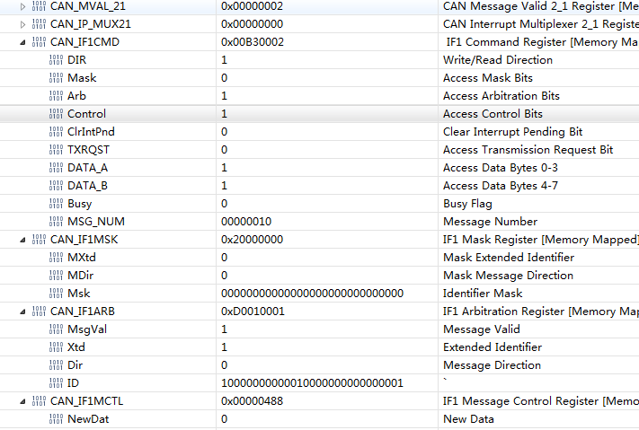
ID过滤的相关寄存器已经赋值为0;

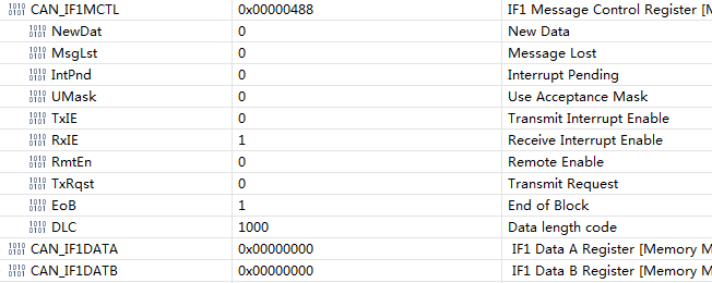
IDMASK = 0;      UMASK=0;

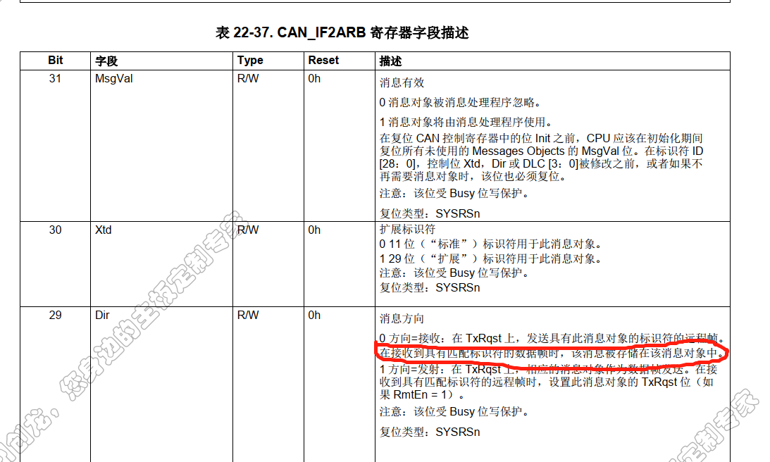
看了一下数据手册,IFxARB->Dir的介绍,

0 Direction = receive: On TxRqst, a remote frame with the identifier
of this message object is transmitted. On reception of a data frame with matching identifier, that message is stored in this message
object.

接收到匹配标识符的数据帧时,消息才会存储?

是不是就这个原因?只能接收对应初始化时ID的数据,如果是的话,怎么设置才能接收任意ID数据?

有知道的帮忙回答一下,TKS

仿真打断点,读取寄存器的值,

  • 1 如果将ID掩码位设置为零,则地址中的该ID位将被忽略。该ID位的任何值都将被接受。

    即 sRXCANMessage.ui32MsgIdMask 为 0

    sRXCANMessage.ui32Flags = MSG_OBJ_RX_INT_ENABLE;

    还要注意ui32MsgIDMask是实际的掩码本身。是否使用接受掩码由UMask位确定。

    在TI例程 C:\ti\c2000\C2000Ware_3_01_00_00\device_support\f2837xd\examples\cpu1\can_external_transmit\cpu01

    就是没有使用过滤,可以接收任意ID的,您可以参考一下

    2 若是使用过滤的话,在过滤之前,将屏蔽位与ID位进行“与”运算。在C中,过滤器如下所示:

    if ((incoming_message_id & mask) == (message_object_id & mask))
    {
        accept_message();
    } else
    {
        ignore_message();
    }


  • 程序就是根据您说的那个例程改的,

    对应的设置也是如上面所说设置的一致的

  • 是否使用接受掩码由UMask位确定,您现在程序中没有对这一位操作吧?

    您的CAN发送发是什么呢?CAN盒还是芯片?
  • 我仿真,打断点,读取了IF1MCTL->UMASK ,IF2MCTL->UMASK,均为0
    使用的CAN盒发送数据
  • 以下是国外同事的回复,请您先参考一下

    Looks like MSG_OBJ_USE_ID_FILTER used. Can you verify the value of tCANMsgObject.ui32Flags and confirm that bit 3 is not set? Bit position is derived from can.h as follows:
    //! This indicates that a message object will use or is using filtering
    //! based on the object's message identifier.
    #define MSG_OBJ_USE_ID_FILTER 0x00000008
  • 已经将对应的bit赋值为0了,

    设置断点,回读IF的设置内容,也是UMASK对应的位为0

    具体如下,

    // Initialize the transmit message object used for sending CAN messages.
    // Message Object Parameters:
    // Message Identifier: 0x5555
    // Message ID Mask: 0x0
    // Message Object Flags: None
    // Message Data Length: 4 Bytes
    // Message Transmit data: txMsgData
    //
    sTXCANMessage.ui32MsgID = 0x10000008;//0x1801ff68;
    sTXCANMessage.ui32MsgIDMask = 0;
    sTXCANMessage.ui32Flags = 0;
    sTXCANMessage.ui32MsgLen = MSG_DATA_LENGTH;
    sTXCANMessage.pucMsgData = txMsgData;

    //
    // Initialize the receive message object used for receiving CAN messages.
    // Message Object Parameters:
    // Message Identifier: 0x5555
    // Message ID Mask: 0x0
    // Message Object Flags: Receive Interrupt
    // Message Data Length: 4 Bytes
    // Message Receive data: rxMsgData
    //
    sRXCANMessage.ui32MsgID = 0x10010001;//0x1801ff68;
    sRXCANMessage.ui32MsgIDMask = 0;//0x1fffffff;
    sRXCANMessage.ui32Flags = MSG_OBJ_RX_INT_ENABLE;
    sRXCANMessage.ui32MsgLen = MSG_DATA_LENGTH;
    sRXCANMessage.pucMsgData = rxMsgData;
    CANMessageSet(CANA_BASE, RX_MSG_OBJ_ID, &sRXCANMessage,MSG_OBJ_TYPE_RX);

    CANMessageSet是直接使用的例程里面的,

    在CANMessageSet设置完成地方设置断点,读取IF1CTL,IF1CMD寄存器的值,也是未使能ID滤波的


  • 我现在是使用C:\ti\c2000\C2000Ware_3_01_00_00\driverlib\f2837xd\examples\cpu1\can 的can_ex1_loopback来进行测试,修改代码后如下

    可以接收其他ID的消息

    主要修改如下:

        CAN_setupMessageObject(CANA_BASE, 2, 0x3FF, CAN_MSG_FRAME_STD,
                               CAN_MSG_OBJ_TYPE_RX, 0x00000000, CAN_MSG_OBJ_USE_ID_FILTER,
                               MSG_DATA_LENGTH);

    //#############################################################################
    //
    // FILE:   can_ex1_loopback.c
    //
    // TITLE:   CAN External Loopback Example
    //
    //! \addtogroup driver_example_list
    //! <h1> CAN External Loopback </h1>
    //!
    //! This example shows the basic setup of CAN in order to transmit and receive
    //! messages on the CAN bus.  The CAN peripheral is configured to transmit
    //! messages with a specific CAN ID.  A message is then transmitted once per
    //! second, using a simple delay loop for timing.  The message that is sent is
    //! a 2 byte message that contains an incrementing pattern.
    //!
    //! This example sets up the CAN controller in "External" Loopback test mode.
    //! Data transmitted is visible on the CANTXA pin and is received internally
    //! back to the CAN Core. It is important that the GPIO mapping in device.h
    //! file in this project is edited to reflect the GPIO pins that are used for
    //! CAN function in your hardware. Otherwise, the transmitted data will not be
    //! seen on CANTXA pin. No interrupts are used.
    //!
    //! Note: "External" loopback does not mean the loopback is done externally.
    //! The loopback is done internally, but the transmitted data can be seen
    //! externally on the CANTX pin.
    //!
    //! \b External \b Connections \n
    //!  - None. (Transmitting node generates its own ACK)
    //!
    //! \b Watch \b Variables \n
    //!  - msgCount - A counter for the number of successful messages received
    //!  - txMsgData - An array with the data being sent
    //!  - rxMsgData - An array with the data that was received
    //!
    //
    //#############################################################################
    // $TI Release: F2837xD Support Library v3.09.00.00 $
    // $Release Date: Thu Mar 19 07:35:24 IST 2020 $
    // $Copyright:
    // Copyright (C) 2013-2020 Texas Instruments Incorporated - http://www.ti.com/
    //
    // Redistribution and use in source and binary forms, with or without 
    // modification, are permitted provided that the following conditions 
    // are met:
    // 
    //   Redistributions of source code must retain the above copyright 
    //   notice, this list of conditions and the following disclaimer.
    // 
    //   Redistributions in binary form must reproduce the above copyright
    //   notice, this list of conditions and the following disclaimer in the 
    //   documentation and/or other materials provided with the   
    //   distribution.
    // 
    //   Neither the name of Texas Instruments Incorporated nor the names of
    //   its contributors may be used to endorse or promote products derived
    //   from this software without specific prior written permission.
    // 
    // THIS SOFTWARE IS PROVIDED BY THE COPYRIGHT HOLDERS AND CONTRIBUTORS 
    // "AS IS" AND ANY EXPRESS OR IMPLIED WARRANTIES, INCLUDING, BUT NOT 
    // LIMITED TO, THE IMPLIED WARRANTIES OF MERCHANTABILITY AND FITNESS FOR
    // A PARTICULAR PURPOSE ARE DISCLAIMED. IN NO EVENT SHALL THE COPYRIGHT 
    // OWNER OR CONTRIBUTORS BE LIABLE FOR ANY DIRECT, INDIRECT, INCIDENTAL, 
    // SPECIAL, EXEMPLARY, OR CONSEQUENTIAL DAMAGES (INCLUDING, BUT NOT 
    // LIMITED TO, PROCUREMENT OF SUBSTITUTE GOODS OR SERVICES; LOSS OF USE,
    // DATA, OR PROFITS; OR BUSINESS INTERRUPTION) HOWEVER CAUSED AND ON ANY
    // THEORY OF LIABILITY, WHETHER IN CONTRACT, STRICT LIABILITY, OR TORT 
    // (INCLUDING NEGLIGENCE OR OTHERWISE) ARISING IN ANY WAY OUT OF THE USE 
    // OF THIS SOFTWARE, EVEN IF ADVISED OF THE POSSIBILITY OF SUCH DAMAGE.
    // $
    //#############################################################################
    
    //
    // Included Files
    //
    #include "driverlib.h"
    #include "device.h"
    
    //
    // Defines
    //
    #define MSG_DATA_LENGTH    2
    
    //
    // Globals
    //
    volatile unsigned long msgCount = 0;
    
    //
    // Main
    //
    void main(void)
    {
        uint16_t txMsgData[2], rxMsgData[2];
    
        //
        // Initialize device clock and peripherals
        //
        Device_init();
    
        //
        // Initialize GPIO and configure GPIO pins for CANTX/CANRX
        //
        Device_initGPIO();
        GPIO_setPinConfig(DEVICE_GPIO_CFG_CANRXA);
        GPIO_setPinConfig(DEVICE_GPIO_CFG_CANTXA);
    
        //
        // Initialize the CAN controller
        //
        CAN_initModule(CANA_BASE);
    
        //
        // Set up the CAN bus bit rate to 500 kbps
        // Refer to the Driver Library User Guide for information on how to set
        // tighter timing control. Additionally, consult the device data sheet
        // for more information about the CAN module clocking.
        //
        CAN_setBitRate(CANA_BASE, DEVICE_SYSCLK_FREQ, 500000, 20);
    
        //
        // Initialize PIE and clear PIE registers. Disables CPU interrupts.
        //
        Interrupt_initModule();
    
        //
        // Initialize the PIE vector table with pointers to the shell Interrupt
        // Service Routines (ISR).
        //
        Interrupt_initVectorTable();
    
        //
        // Enable Global Interrupt (INTM) and realtime interrupt (DBGM)
        //
        EINT;
        ERTM;
    
        //
        // Enable CAN test mode with external loopback
        //
        CAN_enableTestMode(CANA_BASE, CAN_TEST_EXL);
    
        //
        // Initialize the transmit message object used for sending CAN messages.
        // Message Object Parameters:
        //      Message Object ID Number: 1
        //      Message ID: 0x3FF (STDID should be from 0x1 through 0x7FF only)
        //      Message Frame: Standard
        //      Message Type: Transmit
        //      Message ID Mask: 0x0
        //      Message Object Flags: None
        //      Message Data Length: 2 Bytes
        //
        CAN_setupMessageObject(CANA_BASE, 1, 0x3FE, CAN_MSG_FRAME_STD,
                               CAN_MSG_OBJ_TYPE_TX, 0, CAN_MSG_OBJ_NO_FLAGS,
                               MSG_DATA_LENGTH);
    
        //
        // Initialize the receive message object used for receiving CAN messages.
        // Message Object Parameters:
        //      Message Object ID Number: 2
        //      Message ID: 0x3FF (STDID should be from 0x1 through 0x7FF only)
        //      Message Frame: Standard
        //      Message Type: Receive
        //      Message ID Mask: 0x0
        //      Message Object Flags: None
        //      Message Data Length: 2 Bytes (Note that DLC field is a "don't care"
        //      for a Receive mailbox
        //
    //    CAN_setupMessageObject(CANA_BASE, 2, 0x3FF, CAN_MSG_FRAME_STD,
                             //  CAN_MSG_OBJ_TYPE_RX, 0, CAN_MSG_OBJ_NO_FLAGS,
                             //  MSG_DATA_LENGTH);
    
        //
        // Initialize the receive message object used for receiving CAN messages.
        // Message Object Parameters:
        //      Message Object ID Number: 2
        //      Message Identifier: 0x1234
        //      Message Frame: Standard
        //      Message Type: Receive
        //      Message ID Mask: 0x0
        //      Message Object Flags: None
        //      Message Data Length: 2 Bytes
        //
      //  CAN_setupMessageObject(CANA_BASE, 2, 0x1234, CAN_MSG_FRAME_STD,
                            //   CAN_MSG_OBJ_TYPE_RX, 0, CAN_MSG_OBJ_NO_FLAGS,
                             //  MSG_DATA_LENGTH);
    
        CAN_setupMessageObject(CANA_BASE, 2, 0x3FF, CAN_MSG_FRAME_STD,
                               CAN_MSG_OBJ_TYPE_RX, 0x00000000, CAN_MSG_OBJ_USE_ID_FILTER,
                               MSG_DATA_LENGTH);
    
        //
        // Start CAN module operations
        //
        CAN_startModule(CANA_BASE);
    
        //
        // Setup send and receive buffers
        //
        txMsgData[0] = 0x01;
        txMsgData[1] = 0x02;
        *(uint16_t *)rxMsgData = 0;
    
        //
        // Loop Forever - Send and Receive data continuously
        //
        for(;;)
        {
            //
            // Send CAN message data from message object 1
            //
            CAN_sendMessage(CANA_BASE, 1, MSG_DATA_LENGTH, txMsgData);
    
            //
            // Delay before receiving the data
            //
            DEVICE_DELAY_US(1000000);
    
            //
            // Read CAN message object 2 and check for new data
            //
            if (CAN_readMessage(CANA_BASE, 2, rxMsgData))
            {
                //
                // Check that received data matches sent data.
                // Device will halt here during debug if data doesn't match.
                //
                if((txMsgData[0] != rxMsgData[0]) ||
                   (txMsgData[1] != rxMsgData[1]))
                {
                    Example_Fail = 1;
                    asm("   ESTOP0");
                }
                else
                {
                    //
                    // Increment message received counter
                    //
                    msgCount++;
                    Example_PassCount++;
                }
            }
            else
            {
                //
                // Device will halt here during debug if no new data was received.
                //
                Example_Fail = 1;
                asm(" ESTOP0");
            }
    
            //
            // Increment the value in the transmitted message data.
            //
            txMsgData[0] += 0x01;
            txMsgData[1] += 0x01;
    
            //
            // Reset data if exceeds a byte
            //
            if(txMsgData[0] > 0xFF)
            {
                txMsgData[0] = 0;
            }
            if(txMsgData[1] > 0xFF)
            {
                txMsgData[1] = 0;
            }
        }
    }
    
    //
    // End of File
    //
    

  • 感谢,问题已解决
    TI原例程如下, 只能接受固定ID0x5555的数据
    sRXCANMessage.ui32MsgID = 0x5555;
    sRXCANMessage.ui32MsgIDMask = 0;
    sRXCANMessage.ui32Flags = MSG_OBJ_RX_INT_ENABLE;
    sRXCANMessage.ui32MsgLen = MSG_DATA_LENGTH;
    sRXCANMessage.pucMsgData = rxMsgData;
    CANMessageSet(CANB_BASE, RX_MSG_OBJ_ID, &sRXCANMessage,
    MSG_OBJ_TYPE_RX);

    修改为
    sRXCANMessage.ui32MsgID = 0x5555;
    sRXCANMessage.ui32MsgIDMask = 0;
    sRXCANMessage.ui32Flags = MSG_OBJ_RX_INT_ENABLE | MSG_OBJ_USE_ID_FILTER; //此处修改后就可以接受所有ID数据了
    sRXCANMessage.ui32MsgLen = MSG_DATA_LENGTH;
    sRXCANMessage.pucMsgData = rxMsgData;
    CANMessageSet(CANB_BASE, RX_MSG_OBJ_ID, &sRXCANMessage,
    MSG_OBJ_TYPE_RX);
  • 谢谢您的反馈,很高兴能帮到您