This thread has been locked.

If you have a related question, please click the "Ask a related question" button in the top right corner. The newly created question will be automatically linked to this question.

OPA855: Input-Referred Current Noise Simulation with TI-NA

Part Number: OPA855
Other Parts Discussed in Thread: TINA-TI

Dear all

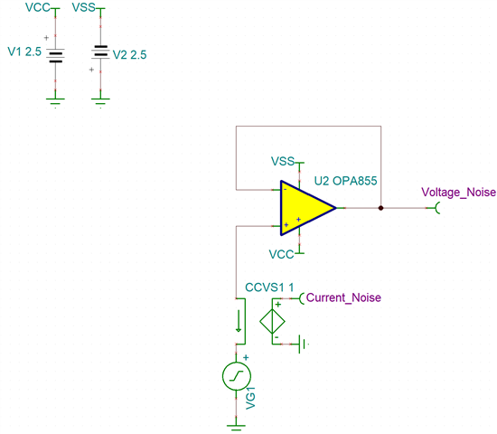
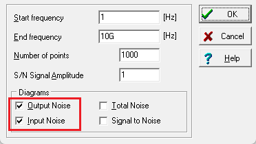
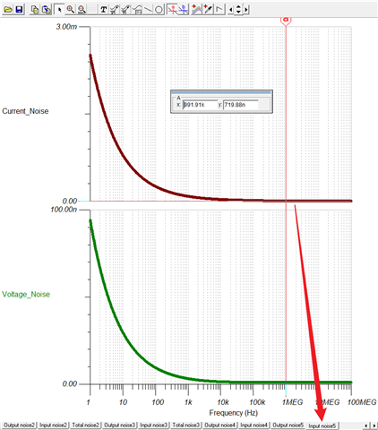
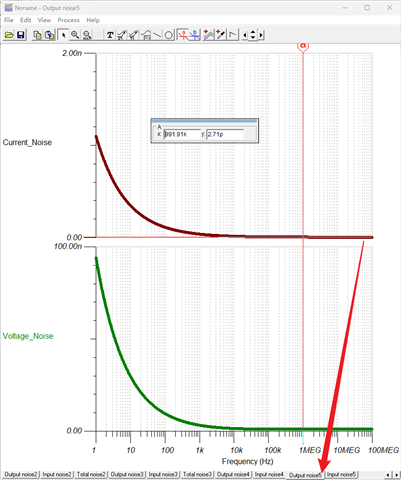
When performing TIA Input-Referred Current Noise simulation, the macro model definition of the OPA855 already includes its input current noise. Why is it that during noise analysis by TINA, only the Output Noise matches the noise curves in the datasheet, while the calculated input noise does not align with the datasheet? Additionally, the simulated input noise shows a larger amplitude in the flat-band region compared to the datasheet. The topology of the simulation circuit is shown below. Thank you for your response. I appreciate it.

  • 感谢您对TI产品的关注!
    关于你的咨询,我们正在确认你的问题,稍后回复您。

  • 期待您的回复,感谢

  • 您好

      感谢您联系并使用 Tina-TI。您说得对, 输入参考电流噪声不正确。由于模型存在单位误差,它比数据手册中显示的数值高出一个数量级。一位用户通过调整 OPA855 网表中的单位误差解决了这个问题:e2e 链接 OPA855 Tina 噪声模型

      对于 Tina-TI 噪声选择:

    1. 输出任意噪声带宽内的 RMS 噪声图。

    • 当启动噪声分析时,输入积分“较低”和“较高”频率。
    • 使用光标读取任意带宽内的 RMS 噪声。  

    2.噪声密度图——指输入或输出。

    • 与信号功率相比,输入参考噪声密度可让您直接观察 SNR。
    • 输出参考密度图以发现可能影响噪声的意外峰值。

      所以:

    TINA-TI“总噪声”图是从分析起始频率到 x 轴值(如果使用游标,则为游标频率)的均方根噪声。“输入噪声”和“输出噪声”图以 V/RtHz 为单位(如果选择电流源作为输入,则以 A/RtHz 为单位)。

    因此,例如,如果放置在 1kHz 处的总噪声光标读取 5.1uV_RMS(如下所示),并且您为 S/N 分析选择“1V”,那么您将读取 105.9dB 的 SNR(=20*log(1V / 5.1uV)= 105.9dB)。

      要测量输入参考电流噪声和输入参考电压噪声,请参阅下面的示例:

      从你的仿真结果来看,你的结果与上例非常相似。输入和输出电压噪声似乎匹配,但输入电流却不匹配,因为电表位于输入端,而 Tina-TI 无法通过该电表计算输出端的噪声。我需要再次确认 Tina-TI 是否能够根据输出电压噪声反算出输入参考噪声(如果涉及增益)。