Part Number: OPA858
Dear Engineer,
I would like to ask a technical question regarding the OPA858DSGEVM board I purchased earlier.
At first, the board did not work when I applied a signal to the inverting input. After reviewing the schematic, I suspected that the 0-ohm resistor R3, which connects the inverting input to ground, might be shorting the signal directly to ground, preventing it from reaching the amplifier. I then removed R3.
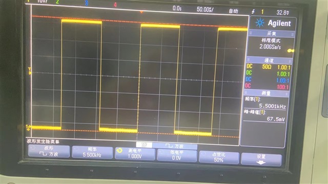
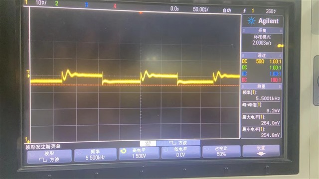
After removing R3 and without connecting VCC and VEE, I applied a square wave signal from an oscilloscope to the inverting input. The signal ranged from 0 V to 500 mV, and the output Vpp was 34 mV. When I increased the input to 0–1 V, the output Vpp rose to 67.5 mV. With a 1.5 V input, the output ranged from 8.8 mV to 87.7 mV. This made me feel the amplifier might be starting to function, because previously, with R3 still in place, the output signal no longer resembled a square wave at all.
Then I tried dual power supply with VCC = +2.5 V and VEE = –2.5 V, but the output Vpp dropped to just 10–20 mV. I then switched to a single supply (VCC = 5 V, VEE = 0 V), but the behavior remained the same.
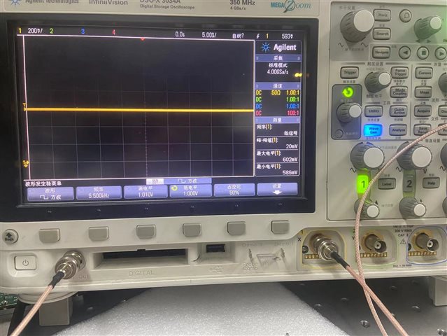
After consulting the OPA858 Op Amp EVM User’s Guide, I noticed there are limitations on the supply voltage range (VCC – VEE), as well as input voltage range restrictions. To stay within spec, I adjusted VEE to 0.4 V and VCC to 3 V. I also set the input square wave to have a low level of 1.00 V and a high level of 1.01 V. However, the output still only showed a Vpp of 10–20 mV, far from the expected gain of ×7.
This makes me wonder if the device might be damaged.
Below is a summary of the attached oscilloscope screenshots:
-
Image 1: No VCC or VEE supplied; input square wave from 0.5 V to 1 V.
-
Image 2: VCC = 3 V, VEE = 1 V; input square wave from 0 V to 1.5 V.
-
Image 3: VCC = 3 V, VEE = 1 V; input square wave from 1.00 V to 1.01 V.
I would appreciate your assistance in determining whether the amplifier is working as expected or if there may be an issue with the EVM.
Thank you very much.