

Part Number: OPA211
您好,
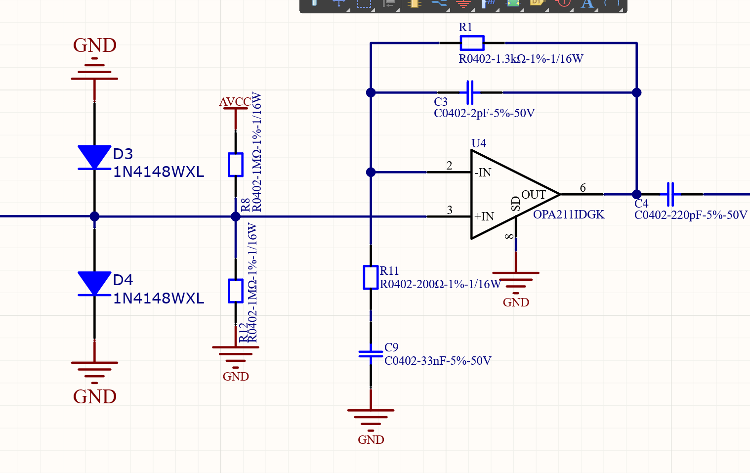
以上是绘制OPA211IDGK的电路图,其中电压AVCC为3.3V,我输入信号设置为80kHZ200mV通过信号发生器产生的一个正弦信号进行输入,但是经过此电路之后测试C4的波形就无法显示正常的信号了失真非常严重。此外只有不断调大信号幅值当为300mv以后才稍微能观测到正弦波信号。这是为什么呢?还是电路图绘制不对呢?
Part Number: OPA211
您好,
以上是绘制OPA211IDGK的电路图,其中电压AVCC为3.3V,我输入信号设置为80kHZ200mV通过信号发生器产生的一个正弦信号进行输入,但是经过此电路之后测试C4的波形就无法显示正常的信号了失真非常严重。此外只有不断调大信号幅值当为300mv以后才稍微能观测到正弦波信号。这是为什么呢?还是电路图绘制不对呢?
