Part Number: PGA854
Dear Expert,
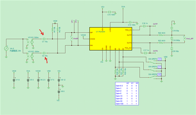
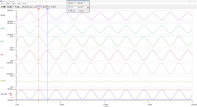
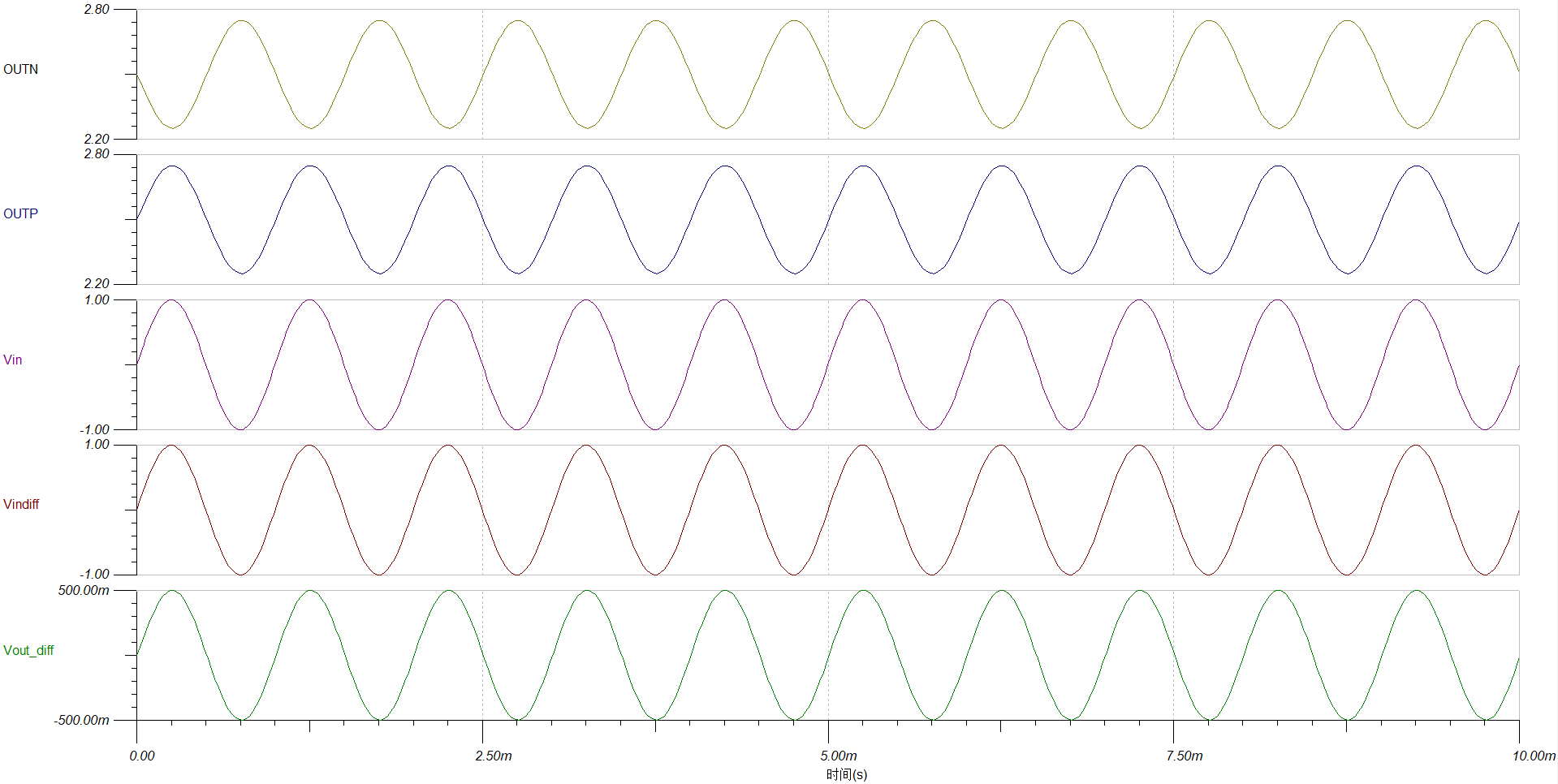
In the simulation circuit shown below, the input signal source is a 1Vpp (peak-to-peak) sine wave at 1kHz. After being amplified by ±0.5x through the VCVS, it is converted into a differential signal and fed into the PGA854. When the amplifier's VS– supply pin is connected to ground, I found that the amplifier output is incorrect. However, when I change the VS– supply to –12V, the output waveform becomes complete. What could be causing this? According to the datasheet, this device should support single-supply operation.
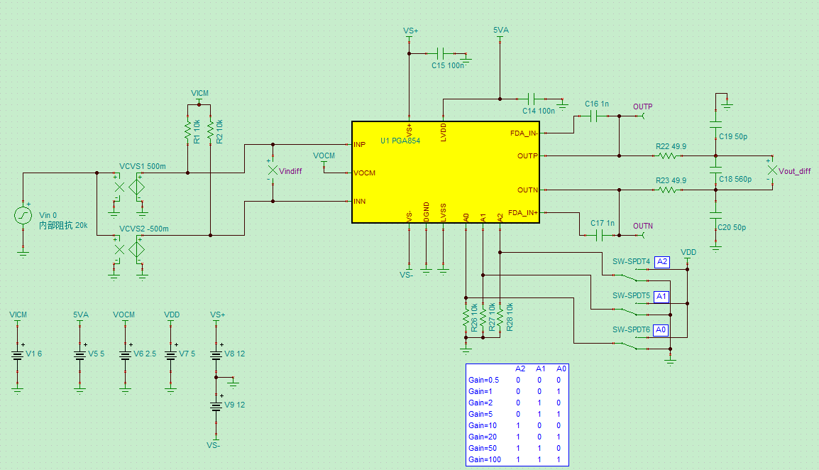
(1) PGA854 VS– pin connected to ground:
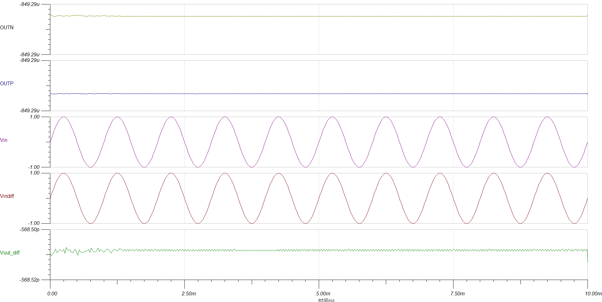
(2) PGA854 VS– pin connected to –12V:
why??I look forward to your reply.Thank you !