This thread has been locked.

If you have a related question, please click the "Ask a related question" button in the top right corner. The newly created question will be automatically linked to this question.

How to explame this figure?

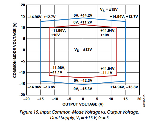
Hello,i'am so sorry to interupt u ! i have read AD8227 for several times,but i still don't know the meaning of this figure.Can you give me a detail explanation of it ? 

What's the purpose of this figure want to express ? thanks for you kind help ! 

  • Hi! Dear, Did you want to know the figure? But it's from ADI. Would you please call them.

  • 这是一个输出电压幅值和输入共模电压范围的一个曲线,分别以+-15V和+-12V为例。

  • 举个简单的例子:

    假设AD8227工作在VS=+-15V,输入共模电压12.7V的情况下,也就是蓝色的曲线的左上角(-14.96V, +12.7V)。

    代表的意义是:

    Vinp = 12.7V + Vdiff/2

    Vinn = 12.7V - Vdiff/2

    由于运放输入共模电压最大值为14.2V,也就是说Vdiff/2最大为14.2V-12.7V = 1.5V,所以Vdiff = 3V,两个方向,也就是+-3V

    放大倍数G=5,也就是差分放大倍数为5。输出理论上是VOUT = 5xVdiff = +-15V,基本刚好可以达到输出最大正负轨供电。(-14.96V, +12.7V)到(+14.94V, +12.7V)这一条直线都在蓝色的曲线内部。

    所以12.7V就是,输出能够达到最大轨对轨的输入共模电压的最大值。

    如果输入共模是14.2V

    也就是

    Vinp = 14.2V + Vdiff/2

    Vinn = 14.2V - Vdiff/2

    由于14.2V已经是输入共模电压的最大值了,所以Vdiff =0, Vdiff/2 =0, 所以Vout = GxVdiff = 0V。不会得到输出,因为差分输入信号为0.

    所以在曲线上,(0, 14.2V)代表的是一个点。

    至于为什么输入共模电压最大值是14.2V,你可以看看规格书第四页,输入共模最大为VS - 0.8V, 如果VS = 15V, 最大共模为14.2V。

    谢谢。

x 出现错误。请重试或与管理员联系。
x 出现错误。请重试或与管理员联系。