

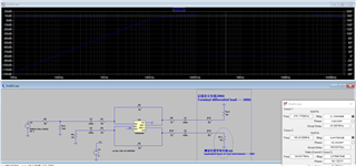
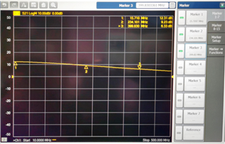
你好,我在使用差分放大器THS4509时,实际测试带宽为234MHz,略大于仿真的190MHz带宽,如下图所示,仿真和实际测试结果基本相同,或者是说,器件的实际表现优于理论仿真。
Hello, when I use the differential amplifier THS4509, the actual test bandwidth is 234MHz, which is slightly larger than the simulated 190MHz bandwidth. As shown in the figure below, the simulation and actual test results are almost identical. In other words, the actual performance of the component is better than the theoretical simulation。
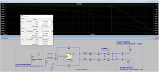
但是当THS4509后面连接LC滤波网络时,实际测试的带宽约为90MHz,远小于理论仿真的164MHz带宽,如下图所示。更换不同电感和电容值,测试结果依然远小于理论仿真,对于这一现象,我想问一下是什么原因可能导致这两种情况的差异。或者说,在仿真时对电路如何补偿,才能做到与实测结果差别不大。
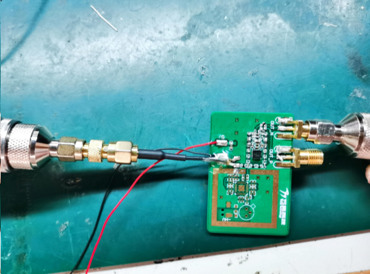
注意:我使用的电感(村田的LQW15系列)、电阻和电容为0402封装,信号线使用较短的同轴线。
But when the LC filter network is connected behind the THS4509, the actual test bandwidth is about 90MHz, which is much smaller than the theoretical simulation bandwidth of 164MHz, as shown in the figure below. After changing different inductance and capacitance values, the test result are still much smaller than the theoretical simulation. For this phenomenon, I would like to ask what may cause the difference between the two situations. In other words, how to compensate the circuit during simulation can achieve little difference from the measured results.
Note: The inductor (Murata's LQW15 series), resistor and capacitor I used are in 0402 package , and the signal lines use shorter coaxial cables。
Thank you.
Chao
