This thread has been locked.
If you have a related question, please click the "Ask a related question" button in the top right corner. The newly created question will be automatically linked to this question.
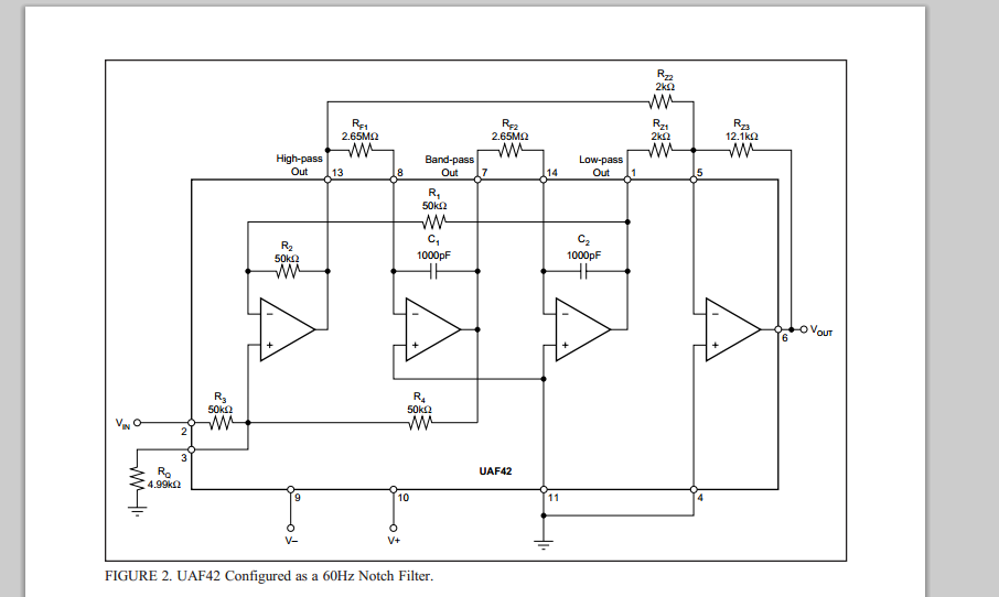
这是60HZ陷波的典型电路,我按照上面的连接后结果仿真结果与理论相差很大,不知道为什么?附件里是我的仿真结果。原理图是:
你好,
仿真中的电阻都严格按照上面的值吗? 能否上传你的仿真结果?
关于60Hz的陷波器,这篇应用笔记有详细的描述:Design a 60Hz Notch Filter with the UAF42 ,可以多看看。
http://www.ti.com/general/docs/lit/getliterature.tsp?baseLiteratureNumber=sbfa012&fileType=pdf
推荐使用TINA仿真,
如果你想用UAF42设计50Hz的陷波器,请参考下面的博文,在第二篇博文上有仿真文件。可以直接复现。
http://www.deyisupport.com/question_answer/analog/amplifiers/f/52/p/64782/148235.aspx#148235
http://www.deyisupport.com/question_answer/analog/amplifiers/f/52/t/64783.aspx