This thread has been locked.
If you have a related question, please click the "Ask a related question" button in the top right corner. The newly created question will be automatically linked to this question.
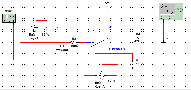
上面是我的仿真电路图,R1的作用是移相,R3的作用是调幅。
然而在实际电路中,输出的波形很不稳定(有很多高频噪声),芯片发热很严重,并且得到的输出的电流也不高。
求问我的电路应该如何修改?本人刚刚开始学习硬件,还请多多包涵,谢谢~
亲;首先;这个电路得用PCB搭,其次;在输出与反向输入端并个5pF电容试试。
谢谢你的回答~工作频率是1Mhz,现在用的是万能板焊接的。5pF电容的作用是滤波吗?我明天去实验室试试看
建议使用电压型放大器实现这样的电路,一般输出波形有高频噪声表示放大器不太稳定。你可以尝试在V+端接个电阻试试。