Part Number: INA818
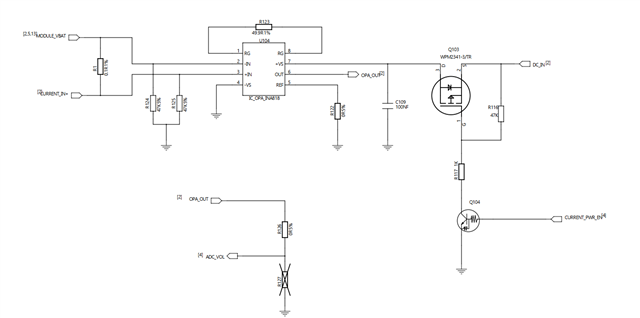
Based on INA818, I designed the current detection circuit. In the differential input of INA818, I selected 0.1R galvanometer resistor and 49.9R gain RG, which can be amplified 1000 times theoretically. However, in the actual test, it was found that the current in the circuit was given 1mA, but there was no output at the output end.

Have any engineers encountered similar situations? Or any good suggestions, thanks.
