

One AIC1106 chip is used as a microphone/speaker PCM data converter. As figure.1 shows.
The works in a 13bit linear mode. With MCLK 2.048MHz and PCMSYNC 8kHz.
I use the AIC1106 output signal as a data source of IF I/Q modulator. First, I found there is a DC offset(about 750Hz ) to drive the center frequency 45MHz high. But when large signal exists, the influence is quite small. But when the audio signal mute, the DC offset influence appears significant, this cause an hundreds to kilo Hz noise when audio muted.
I check the AIC1106 dirver waveform. The MCLK and PCMSYNC waveform and the PCMSYNC and PCMOUT waveform as Figure.2 and Figure.3 shows, respectively.
The logic level and timing is correct.
As Figure.4, when large signal input exist, can not find anything wrong as the waveform shows. But when the input signal eliminated, the waveform obviously unusual. The 6th bit form LSB is always high. Different signal level input has been tested. The 6th bit has the same behavior. When signal is small enough( a very small range), the 0th bit to 5th bit (count form LSB) varies but the 6th bit keep high.
Finally, I believe the 6th bit unsual behavior causes the I/Q modulator output a wrong IF frequency with about 750Hz freq DC offset (I added a 300HPF to eliminate the mute noise( whistle).
My question is:
1. Is the application circuit correct ?
2. If the circuit is correct ( I can't find any thing wrong till now). The 6th bit unusual cause by chip bug?
3. Any software technic can avoid this?
Hope give me a reply to help me to use the AIC1106 in my project. Thanks ahead.
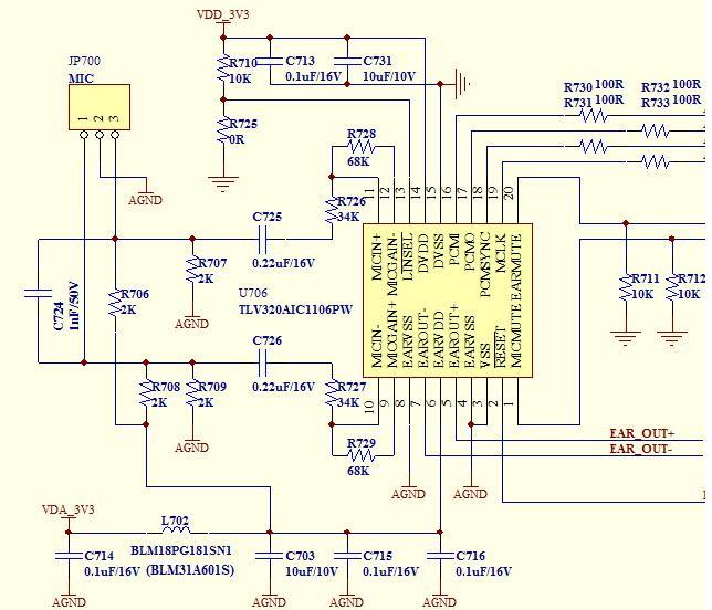
Figure.1 Main part of TLV320AIC1106 application circuit.

Figure.2 The MLCK and PCMSYNC waveform.

Figure.3 The PCMOUT waveform when large signal input

Figure.4 The PCMOUT waveform when signal off.

Figure.5 The PCMOUT waveform when signal off.

