This thread has been locked.

If you have a related question, please click the "Ask a related question" button in the top right corner. The newly created question will be automatically linked to this question.

TLV320ADCX140SW-DRIVERS: The SDOUT Pin no any data

Part Number: TLV320ADCX140SW-DRIVERS
Other Parts Discussed in Thread: TLV320ADC6140

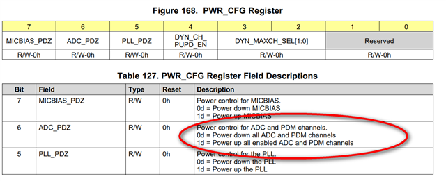
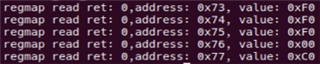
I use 4 analog microphones through differential input, but SDOUT has no data, I checked the registers and found that the 0x76 register shows that my chip is not working properly, do I need to turn on any switches?

Thanks

  • 您好,0x76 这里读取的值为0x00,说明ADC和PDM的所有通道都power down了。

    您需要通过寄存器0x75 bit6配置为1将其power up。

  • Hi Kailyn:

    感谢你的支持! 我已经尝试过把寄存器0x75设置为0xE0, 但SDOUT依然没有任何数据. 以下是我所尝试过的更多信息.

    1. 当我使用Linux动态加载该驱动时, 我通过逻辑分析仪抓取了I2C数据如下:

    -------

    98 01 01

    98 02 81

    98 21 00

    98 73 C0

    98 74 C0

    98 75 E0

    98 76 99 00 // 读数据

    98 77 99 C0 // 读数据

    98 75 00

    98 07 70

    98 75 E0

    -------

    按照文档要求, 我重点对寄存器0x73, 0x74, 0x75进行了初始化. 为了验证问题出现在哪里, 我在初始化完成这几个寄存器读取了寄存器0x76值为0x00, 表明没有任何通道被使能.

    2. 然后我使用arecord工具进行录音时, 逻辑分析仪抓取了I2C数据如下:

    -------

    98 75 00

    98 75 E0

    98 15 99 FF  // 读数据

    98 76 99 00  // 读数据

    98 77 99 C0  // 读数据

    -------

    我同时抓取了I2S的波形, 该时钟由主控提供, TLV320ADC6140为从设备.

    BCLK: 3.072MHz

    FSYNC: 48KHz

    SDOUT: 出现一些不规律杂波, 软件解读数据都为0xFFFFFFFF 

    3. 为了进一步确认问题, 我看到寄存器0x15能做PLL的检查, 我不确定作为TLV320ADC6140作为从设备时该寄存器值是否有效, 但我读出来的值(0xFF)不是我的预期值. 查询datasheet可知该值表示Invalid sample rate和invalid ratio.

    能请您帮我分析一下我的问题出在哪里吗?

  • 您好,时序中写完寄存器0X15之后收到ACK信号,然后应该是发送一个stop 命令,然后再restart+slave address+read + register data。

    所以我看时序里,我红色标注的这里,好像是不满足stop的要求,当clock为高时,data由低变高为stop 命令。我怀疑是这里的问题导致读取的值为0XFF。