This thread has been locked.

If you have a related question, please click the "Ask a related question" button in the top right corner. The newly created question will be automatically linked to this question.

TPA3132D2: How to design TPA3132D2 heat dissipation?

Part Number: TPA3132D2

Hello!

The case is we used TPA3132 amplifier to drive two 20w 8ohm trumpet.

In hardware our design didn't used power limited, connect Pin:PLIMIT to GVDD directly. And we design to the slave mode with 36dB gain, with none of other external radiator.

Isn't for those reasons the amplifier couldn't working over 3 secounds with a normal statue, then it would be turn off by itself with Pin: FAULTZ set low. 

And i did another test also. Colding the amplifier with dry ice, and setting the dry ice around the amplifier. Finally, it could be working normally! 

Therefore, my doubt is how to design TPA3132 heat dissipation, it must working with the external radiator or I can optimize my design to solve this problem?
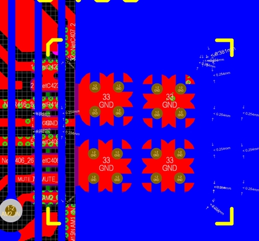
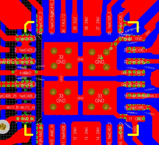
Here is the design layout Schematic diagram is over it.  

  • Thank you for contacting TI China E2E forum and choosing our products as part of your solution.
    Regarding your query, it looks like insufficient heat dissipation area of your design.
    Datasheet gives you Layout Guidelines and Thermal Design in section 10.1 to 10.3.

    www.ti.com/.../tpa3132d2.pdf

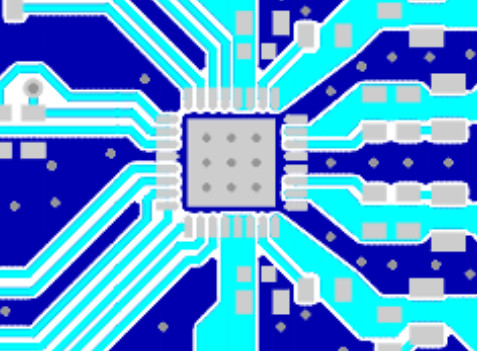
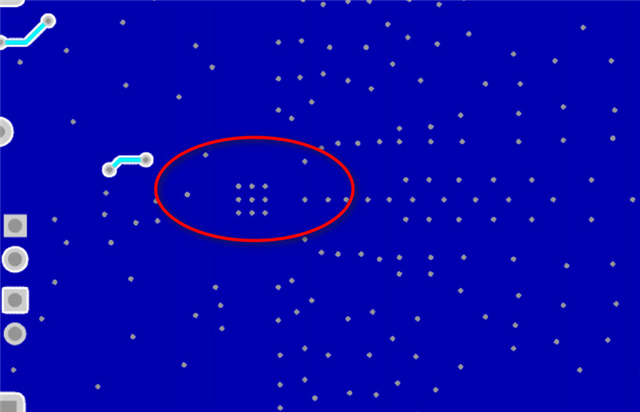
    Please refer to our evaluation board design.
    www.ti.com/.../slou375.pdf

    top side

    .


    bottom side.


    We also provide our EVM's Gerber data for your reference, you can use CAM350 to open it.
    TPA3131-32-33D2EVM RevA Gerber Files
    https://www.ti.com/lit/zip/sloc294

    Thanks.

  • Hello FRANK!

    I also try to scrape off the solder mask around amplifier bottom area of my pcb, then add lots of solder between bottom via and ground. Unfortunately it is still not working.

    At the first times I used 24v power to supply amplifier, it is not working.

    And I try to change the voltage of supply into 12v, The amplifier could working as normal. After working for 30 minutes, the temperature rise of it doesn't exceed 20℃.

    In summary,  it was cause by high internal resistance of the chip. However with the develop of voltage, chip's tempeture  would be much more higher.

  • The bottom side of large ground, will improve the heating too fast.