If you have a related question, please click the "Ask a related question" button in the top right corner. The newly created question will be automatically linked to this question.
RE: TLV320ADC5140: TLV320ADC5140 Unable to capture sound
Assuming that these registers were read back while the recording is in progress, as mentioned above, device is indicating an invalid BCLK and FSYNC input.
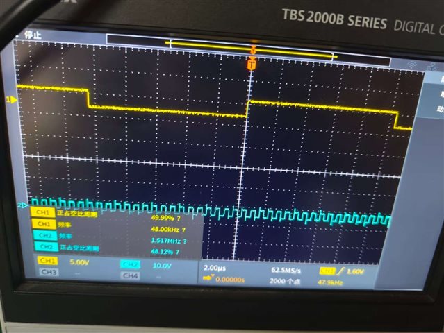
1) Is it possible to confirm the BCLK and FSYNC inputs to the device are as expected using oscilloscope?
2) Can we also update these two register configurations?
ADC_DATE_INPUT(0x16 , 0x08) - this was written as 0x88, which makes the ADC clock source as MCLK in master mode with PLL disabled case. Since the PLL is enabled in this configuration, we can use the BCLK as source clock.
ADC_DATE_INPUT(0x1F , 0x41); //Reserved field is being overwritten when making this 0x01, default value is 0x40
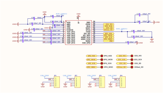
Hello, I have updated the register. Here are the waveforms of BCLK and FSYNC that I captured with the oscilloscope, along with my ADC5140 peripheral circuit diagram. Are there any errors in my ADC5140 peripheral circuit design? Thank you.
1) It looks like all the decoupling capacitors used are 100nF. Please refer to application section in datasheet for decoupling recommendations.
2) I am seeing that the SDOUT pin is connected to I2S3_SD of the STM controller, and GPIO1 pin is connected to I2S3ext_SD pin of the controller. The SDOUT is a data output from the ADC, Can we confirm whether the I2S3_SD is a data input or output for the STM controller?