This thread has been locked.

If you have a related question, please click the "Ask a related question" button in the top right corner. The newly created question will be automatically linked to this question.

LMX2594: LMX2594 锁定时间

Part Number: LMX2594

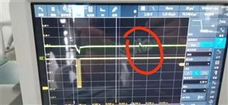
上图所示:SPI时钟频率为25MHz,黄色线为spi时钟,绿色线为lmx2594的压控电压。跳频时发现压控电压温度在100us后又出现一个较大的波动(红色圈所示)。每个频点都会有这个,只是中间间隔时间不同。为什么会出现这个?有什么解决方式?

2、《Streamline RF Synthesizer VCO Calibration and Optimize PLL Lock Time 》这个文档中介绍的锁定时间只有50us以内。我目前安装VCO自动校正、部分辅助模式、完全辅助模式分别测试,VCO分段内跳频时间可以做到50us左右,跨段跳锁定时间不定,最长170us左右。请问这个配置有什么特殊的吗?需要注意哪些问题。

  • 您好,抱歉回复晚了,您的这个问题我需要再去确认下。

  • 您好,抱歉回复晚了,绿色压控电压波形指的是Vtune电压还是Lock detect 电压?

    关于锁存时间,跳频时,参考full assist  mode。建议将您配置的文件和过程附上,我这边分析下?

  • 在使用过程中我也需要这种情况,跳频时,稳定到目标频点后会出现毛刺,导致跳频时间大幅度加长,跟手册所说的不一致。这种不稳定也一直没有找到原因。

  • 您好,因为这个帖子的时间比较长了,建议您重新建一个新帖子,如果和这个问题类似,建议将您的波形,配置文件都附上,我这边看下。

  • The MUXout pin can be configured to output a signal that gives an indication for the PLL being locked. If the
    MUXout pin is configured as a lock detect output (MUXOUT_LD_SEL = 1), the MUXout pin output is a logic
    HIGH voltage when the device is locked. When the device is unlocked, the MUXout pin output is a logic LOW
    voltage.
    There are options to select the definition of PLL being locked. If LD_TYPE = 0, lock detect asserts a HIGH output
    after the VCO has finished calibration and the LD_DLY timeout counter is finished. If LD_TYPE = 1, in addition to
    the VCO calibration and counter check, lock detect will assert a HIGH output if the VCO tuning voltage is also
    within an acceptable limits.

    MUXout 引脚可以配置为输出一个信号,指示 PLL 被锁定。 如果 MUXout 引脚配置为锁定检测输出 (MUXOUT_LD_SEL = 1),则器件锁定时 MUXout 引脚输出为逻辑高电平电压。 当器件解锁时,MUXout 引脚输出为逻辑低电平电压。
    有选项可以选择锁定 PLL 的定义。 如果 LD_TYPE = 0,在 VCO 完成校准并且 LD_DLY 超时计数器完成后,锁定检测断言一个高电平输出。 如果 LD_TYPE = 1,除了 VCO 校准和计数器检查之外,如果 VCO 调谐电压也在可接受的范围内,锁定检测将断言 HIGH 输出。

  • 您好,您是有什么问题吗? 如果有什么问题,为了更好的跟进您的问题,也是建议您新建一个帖子。