Part Number: CDCEL913
Other Parts Discussed in Thread: CDCE913, CLOCKPRO,
/** CDCEL913芯片外接晶振频率 单位:kHz*/
#define CLK_IN    12000

/**
* @Description:调整ad芯片的输入频率
* @param f_out 目标频率 单位:百Hz
* @return NULL
*/
void CDCE_Init_set(float f_out)
{


    uint8_t i = 0;
    uint32_t correctnum = 0;
    uint32_t M, N,  Q, R;
    float Pdiv;
    uint8_t reg18, reg19, reg1A, reg1B;
    int32_t P;
    float f_vco = 0;
    uint8_t f_odr=1;
    printf("f_out:%f\r\n", f_out);
    //a = (float)(f_out / (float)1000.0f);

    f_out = (f_out / 1000.0f);
    printf("f_out :%f\r\n", f_out);
begin:
    i = 0;
    f_vco = f_out;
    printf("f_vco :%f\r\n", f_vco);
    f_odr = f_vco/1000;
    bool result    = false;
    uint8_t f_range;

    if (f_out <= 0) return;

    if(f_odr<8)
    {
            while (f_vco < f_odr*12 * 1000)
                {
                    i++;
                    f_vco = f_out * i;
                }
            }
    else
    {
                while (f_vco < 84 * 1000)
                {
                    i++;
                    f_vco = f_out * i;
                }
    }


    while (f_vco < 231 * 1000)
        {
            for (N = 4095; N > 0; N--)
                {
                    for (M = 511; M > 0; M--)
                        {
                            if(((uint32_t)(f_vco * 1000) % 1000 == 0))
                                {
                                    if ((uint32_t)((N * (CLK_IN) / M)) == (uint32_t)(f_vco))
                                        {

                                            result = true;
                                            break;
                                        }
                                }
                            else
                                {
                                    if(((uint32_t)((float)N * (float)(CLK_IN) / (float)M) + correctnum) == (uint32_t)((f_vco * 1000) / 1000))
                                        {
                                            {

                                                result = true;
                                                break;
                                            }
                                        }
                                }
                        }

                    if (result)
                        {
                            break;
                        }
                }

            if (result)
                {
                    break;
                }
            else
                {
                    i++;
                    f_vco = f_out * i;
                }
        }

    printf("M:%d\r\n", M);
    printf("N:%d\r\n", N);
    printf("f_vco:%f\r\n", f_vco);

    if(((M == 0) && (N == 0)) || (f_vco > 231 * 1000))
        {
            if(correctnum < 11)correctnum++;
            else correctnum = 1;

            printf("refind M N\r\n");
            goto begin;
        }

    P = 4 - (int)((log((double)N / (double)M)) / log(2));

    if (P < 0)
        {
            P = 0;
        }

    Q = (int)((double)N * pow(2, (double)P) / (double)M);
    R = (double)N * pow(2, (double)P) - M * Q;


    if (f_vco < 125 * 1000)
        {
            f_range = 0;
        }
    else if ((f_vco >= 125 * 1000) && (f_vco < 150 * 1000))
        {
            f_range = 1;
        }
    else if ((f_vco >= 150 * 1000) && (f_vco < 175 * 1000))
        {
            f_range = 2;
        }
    else
        {
            f_range = 3;
        }


    Pdiv = (uint32_t)(f_vco) / (uint32_t)(f_out);
    printf("f_vco:%f\r\n", f_vco);
    printf("Pdiv:%d\r\n", (uint8_t)Pdiv);
    cdce913_I2C_WriteByte(0x02, 0xB4);
    cdce913_I2C_WriteByte(0x03, (uint8_t)Pdiv);
    cdce913_I2C_WriteByte(0x04, 0x02);
    cdce913_I2C_WriteByte(0x05, 0x50);
    cdce913_I2C_WriteByte(0x06, 0x40);

    cdce913_I2C_WriteByte(0x10, 0x00);
    cdce913_I2C_WriteByte(0x11, 0x00);
    cdce913_I2C_WriteByte(0x12, 0x00);
    cdce913_I2C_WriteByte(0x13, 0x00);
    cdce913_I2C_WriteByte(0x14, 0x0d);        //Y2,Y3开关控制,y1不是该引脚控制,固定有Y1
    cdce913_I2C_WriteByte(0x15, 0x02);

    cdce913_I2C_WriteByte(0x16, 0);
    cdce913_I2C_WriteByte(0x17, 0);

    reg18 = (N >> 4) & 0xFFF;
    reg19 = (N & 0xf) << 4 | (R & 0xf0) >> 5;
    reg1A = (R & 0x1f) << 3 | ((Q >> 3) & 0x7);
    reg1B = (Q & 0x7) << 5 | (P & 0x07) << 2 | (f_range & 0x03);


    cdce913_I2C_WriteByte(0x18, reg18);
    cdce913_I2C_WriteByte(0x19, reg19);
    cdce913_I2C_WriteByte(0x1A, reg1A);
    cdce913_I2C_WriteByte(0x1B, reg1B);

    cdce913_I2C_WriteByte(0x1C, N);
    cdce913_I2C_WriteByte(0x1D, ((N & 0xf) << 4) | (R & 0xf0));
    cdce913_I2C_WriteByte(0x1E, (R & 0x0f) | (Q & 0xf0));
    cdce913_I2C_WriteByte(0x1F, ((Q & 0x07) << 5) | ((P & 0x07) << 2) | (f_range & 0x03));
    /** 使能时钟输出*/
    HAL_GPIO_WritePin(CLK_CTRL_S0_GPIO_Port, CLK_CTRL_S0_Pin, GPIO_PIN_SET);


}
f_out:1196032.000000
f_out :1196.031982
f_vco :1196.031982
bbbbbbb
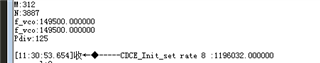
M:498
N:546
f_vco:13156.351563
f_vco:13156.351563
Pdiv:11
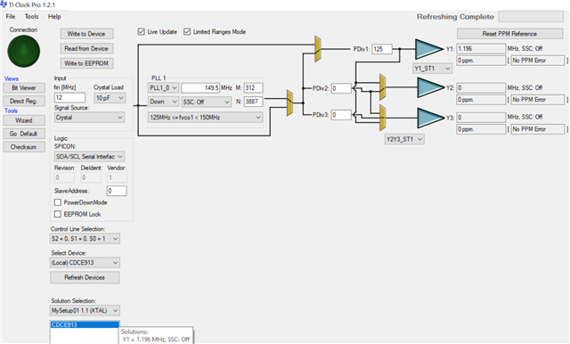
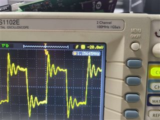
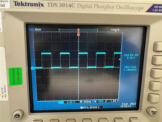
我的目标输出为1196kHz,
但是示波器测量到频率为1160kHz。
但是我用这个代码去计算和设置cdce913的某些频率却是正确的。所以我可以确认是软件计算的 M,N的数值有问题。项目马上交付发现这个问题,希望能尽快解决掉。我看论坛和网上也几乎没有相关的驱动程序。