This thread has been locked.

If you have a related question, please click the "Ask a related question" button in the top right corner. The newly created question will be automatically linked to this question.

TPL8002-25: How to use TPL8002-25 as a resistance?

Part Number: TPL8002-25

I have some trouble about tpl8002-025, the chip of parallel input function is what I need.

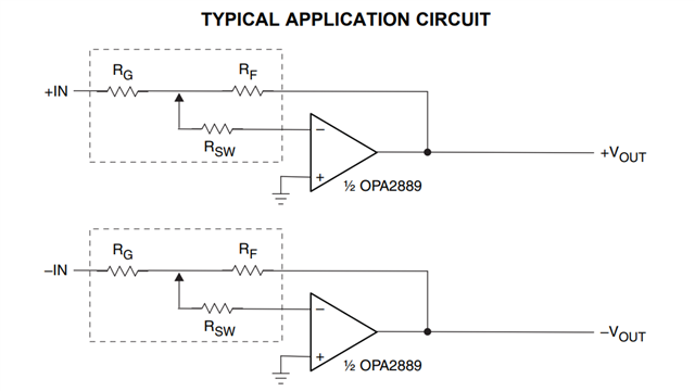
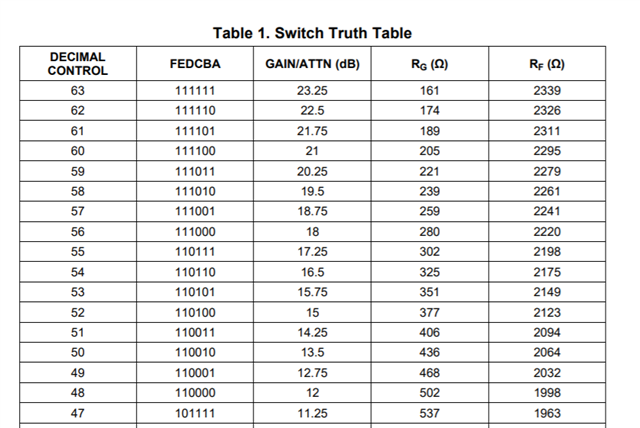
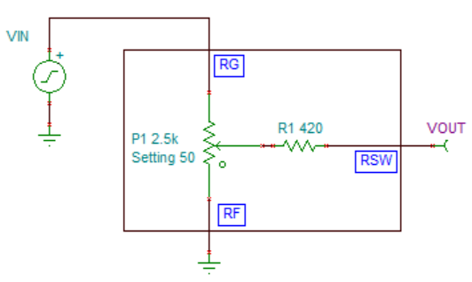
I have connected VCC/VEE  with +- 3.5V,  Pins 10-15 are hooked with 3.5V( for test), Pins 9 and 16 are hooked with GND.I wonder know how to measure the value of RG RF and RSW.I I just wanna output the resistance, and not use in operational amplifier circuit. How get I use it as a resistance.

I want to use this chip to control LED brightness Dynamically,  which is high frequency.

  • Hello, TPL8002 need to use the operational amplifier to decide the RF, RG and RSW value according to the function truth table. So if not use the OP, I don't understand your meaning completely. 

  • If I don't use the operational amplifier, is there no way for RF  RG and RSW to output values according to the function truth table?

    I just need a Digital potentiometer with parallel input and high bandwidth to control the resistance value.

  • The series wiper resistance for each wiper tap terminal, RSW, is set to 420Ω. RG and RF are given in the Switch Truth Table (Table 1) in the datasheet. If pins 10-15 are connected to 3.5V for test then RG will be 161 and RF will be 2339Ω.

    In this diagram, VIN is applied to RG, GND is applied to RF and VOUT is on RSW. RG and RF create a voltage divider: VOUT= VIN*RF/(RG+EF)

  • Thanks for your answer sincerely. I see,I learn to use voltage divider with TPL8002-25. But if I want to use only the value of RF in series to a certain circuit, can it be achieved? I hope it can be used as a sliding rheostat for me

  •  Yes you may just use RF in the circuit. To do this, leave the RG pin floating and connect the RF and RSW pins to your circuit. The 420Ω series resistance of RSW is fixed so it will be added to the values given in the table for RF. This means the minimum resistance between the RF and RSW terminals will be 568Ω and the maximum resistance will be 2759Ω.