

Part Number: ADS131M02-Q1
Other Parts Discussed in Thread: ADS131M08
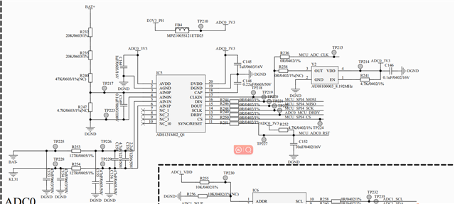
这是原理图部分
 ,
,
我的配置clkin是8Mhz,OSR设置是16384,gain设置是1,想问下最大的测量范围,是否能测量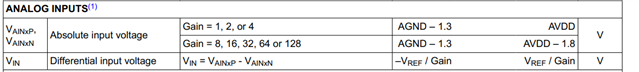 范围内电压
范围内电压
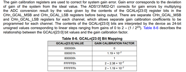
当我输入为0.068V时,用131测量,根据公式  乘上channal1中的值,计算出来是0.069V,偏差其实有些大,问下您我是否计算有问题
Part Number: ADS131M02-Q1
Other Parts Discussed in Thread: ADS131M08
这是原理图部分
,
我的配置clkin是8Mhz,OSR设置是16384,gain设置是1,想问下最大的测量范围,是否能测量范围内电压
当我输入为0.068V时,用131测量,根据公式 乘上channal1中的值,计算出来是0.069V,偏差其实有些大,问下您我是否计算有问题

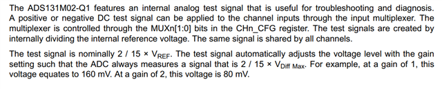 呢我是否需要根据这里去做偏差补偿计算,gain为1和2时,我可以计算多少的偏差去把读到的值补偿一下,gain为4/8....的时候我该如何计算,或者有没有计算公式,还是不需要做补偿计算
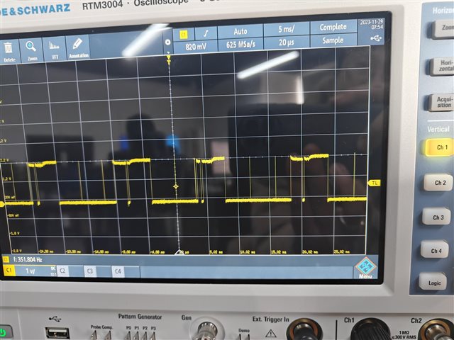 有一些不再期望内的脉冲,