This thread has been locked.

If you have a related question, please click the "Ask a related question" button in the top right corner. The newly created question will be automatically linked to this question.

ADS131A02: 读写寄存器均正常,但是读出数据为0

Part Number: ADS131A02

请求各位大佬不吝指导,确实不知道该怎么办了……

ADC读写寄存器均正常,但是数据转换后,得到的数据为 0x2200 0000 0000 0000 0000

用示波器看DRDY输出波形,一直为高电平,应该是说明没有开始转换。

配置数据位:M0高电平,M1高电平,M2低电平

原理图:

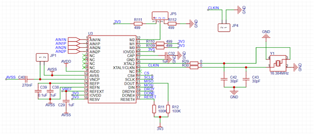
基本和官方给出的设计文档一致,参考电压采用内部电压,寄存器配置如下

A_SYS_CFG:0x68
D_SYS_CFG:0x3e

无源晶振:16.384Mhz分频,8 8 4096
  • 您好,

    datasheet Figure 106. ADS131A0x Configuration Sequence 有初始化流程,您是按照Figure 106配置启动的AD转换吗?

    DRDY一直高 不知道是不是 因为没有启动AD转换?您是怎样启动AD转换的?

  • 您好,非常感谢您的回答,我把启动代码贴在下面。初始化流程是按照流程图和参考例程过来的。

    void adcStartup(void) {
        HAL_Delay(100);
    
        HAL_GPIO_WritePin(GPIOC, GPIO_PIN_8, GPIO_PIN_SET);
    
        restoreRegisterDefaults();
    
        // Always send a NULL command before sending a new command
        HAL_Delay(5);
    
        sendCommand(OPCODE_NULL);
    
        uint16_t response = sendCommand(OPCODE_NULL);
        if (response != 0xFF02) {
            assert(0);
        }
        printf("response: %x\n", response);
    
        unlockRegisters();
    
        uint8_t regVal = D_SYS_CFG_DEFAULT;
    #ifdef SET_FIXED
        regVal |= D_SYS_CFG_FIXED_MASK;
    #endif
    
    #ifdef SET_CRC_EN
        regVal |= D_SYS_CFG_CRC_EN_MASK;    // Set CRC_EN bit
    #endif
    
    #ifdef SET_CRC_MODE
        regVal |= D_SYS_CFG_CRC_MODE_MASK;  // Set CRC_MODE bit
    #endif
        // Write to D_SYS_CFG_ADDRESS
        writeSingleRegister(D_SYS_CFG_ADDRESS, regVal);
    
        // Write to A_SYS_CFG_ADDRESS
        writeSingleRegister(A_SYS_CFG_ADDRESS, 0x68);
    
        // Config data rate
        writeSingleRegister(CLK1_ADDRESS, CLK1_CLK_DIV_8);
        writeSingleRegister(CLK2_ADDRESS, CLK2_ICLK_DIV_8 | CLK2_OSR_400);
    
        // Enable all ADC channels
        writeSingleRegister(ADC_ENA_ADDRESS, ADC_ENA_ENA_ALL_CH_PWUP); // 0x0F
    
        /* (REQUIRED) Always send a NULL command first to establish SPI communication */
        sendCommand(OPCODE_WAKEUP); // 0x0033
    
        lockRegisters();
    
        // Ignore the first 3-4 conversion results to allow for the
        // output buffers to fill-up and the SINC3 filter to settle
        uint8_t ignore_counter = 4;
        AdcDataStruct dummy_data;
        while (ignore_counter > 0) {
            readData(&dummy_data);
            ignore_counter--;
        }
    }

  • 我在wakeup命令中验证:

    sendCommand(OPCODE_NULL);
    sendCommand(OPCODE_WAKEUP); // 0x0033
    response = sendCommand(OPCODE_NULL);
    printf("ADS131 OPCODE_WAKEUP,response: %x\n", response);
    经过验证,发现response确实为0x0033,但是没有启动转换,这是什么原因呢
  • 供电电压AVDD\AVSS 是多少?测量电压正常吗?

    JP1是否连接?

    基准电压实测正常吗?

    晶振是否起振,频率是否正常?

  • 后续发现了问题所在,是由于晶振用的负载电容不对,应该是30pf,结果放了个比较大的电容上去,所以出错了。

    之前不知道系统哪里出问题了,我没有办法回复,今天才想起来回复您。感谢您的指导!

  • 不客气,很高兴您的问题已解决,感谢您的反馈!

    也很抱歉,系统出问题造成您无法回复。