Part Number: ADS1285
I used three ADS1285s in my PCB. I configured them to sample at 1000SPS. The actual data output rate detected was 976.6Hz, which is consistent with the expected rate. In my previous test, I used the pulse-sync mode, and the chip drdy frequency was 976.6Hz, which was consistent with the expected rate. Next, I configured the ads1285 to continuous-sync mode, and output a PWM wave through the microcontroller to provide a synchronization signal for the ads1285. The datasheet describes that when the drdy frequency differs from the sync signal frequency by several clock cycles, the ads1285 will resynchronize. During my test, I found that the signal frequency always stay the same as the PWM frequency, unless I output the PWM frequency exceeding 976.6 (which would cause DRDY to fail to output a signal). When my PWM frequency is lower than 976.6, the output drdy signal freq of ADS1285 decreases accordingly. What makes me wonder is whether its sampling rate will decrease at the same time; or only the DRDY signal rate changes, while the internal sampling rate remains unchanged? And when(at which moment?) the sample happened? When will the resync occur?
here is the datasheet words:------------------
8.4.4.2 Continuous-Sync Mode
After synchronization, DRDY continues to pulse; however, data are held low for 63 data periods to allow for the digital filter to settle. See fig 6-4 for the DRDY behavior. Because of the initial delay of the digital filter, the SYNC input signal and the DRDY pulses exhibit an offset time. The offset time is a function of the data rate.
-------------------------------------------
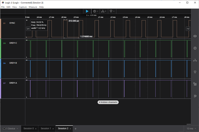
The following is a logic analyzer waveform of the SYNC signal and the DRDY signal, showing that the DRDY signal is fully synchronized with the SYNC signal, all of them are at 784.878Hz (ADS synchronization mode is Continuous-Sync Mode, sample rate configuration is 1000SPS, and operating clock frequency is 8MHz).
我的PCB中使用了三片ADS1285,我将他们配置为1000SPS采样速率,实际检测到的数据输出速率为976.6Hz,这与预期的速率符合。在我前面的测试中,我使用的是脉冲同步模式(Pulse-Sync Mode),芯片drdy频率是符合预期的976.6Hz。接下来我将ads1285配置为连续同步模式(Continuous-Sync Mode),并通过单片机输出一路PWM波,为ads1285提供同步信号。数据手册中描述,当drdy频率与sync信号频率相差为数个时钟周期时,ads1285将发生重新同步。在我测试过程中,我发现信号的频率始终与PWM频率保持相同,除非我输出PWM频率超过了976.6(这会导致DRDY无法输出信号)。当我的PWM频率低于976.6时,ads1285的输出数据速率随之降低,让我疑惑的是其采样速率是会同时降低;还是仅变化了drdy信号速率,而内部采样速率是保持不变的。ADC采样是何时(在哪一刻)发生的,什么时候会发生重新同步?
以下是SYNC信号与DRDY信号的逻辑分析仪波形,显示DRDY信号与SYNC信号完全同步,他们的频率均为784.878Hz(ADS同步模式为Continuous-Sync Mode,采样速率配置为1000SPS,工作时钟频率为8MHz)。