If you have a related question, please click the "Ask a related question" button in the top right corner. The newly created question will be automatically linked to this question.
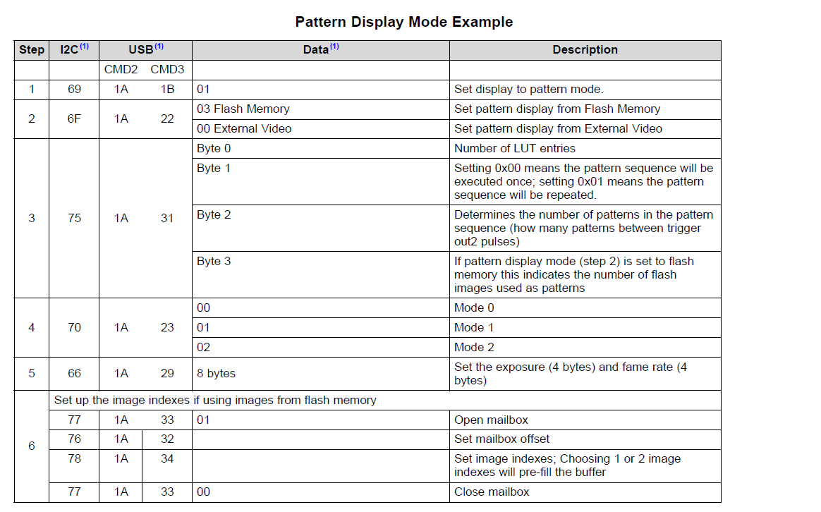
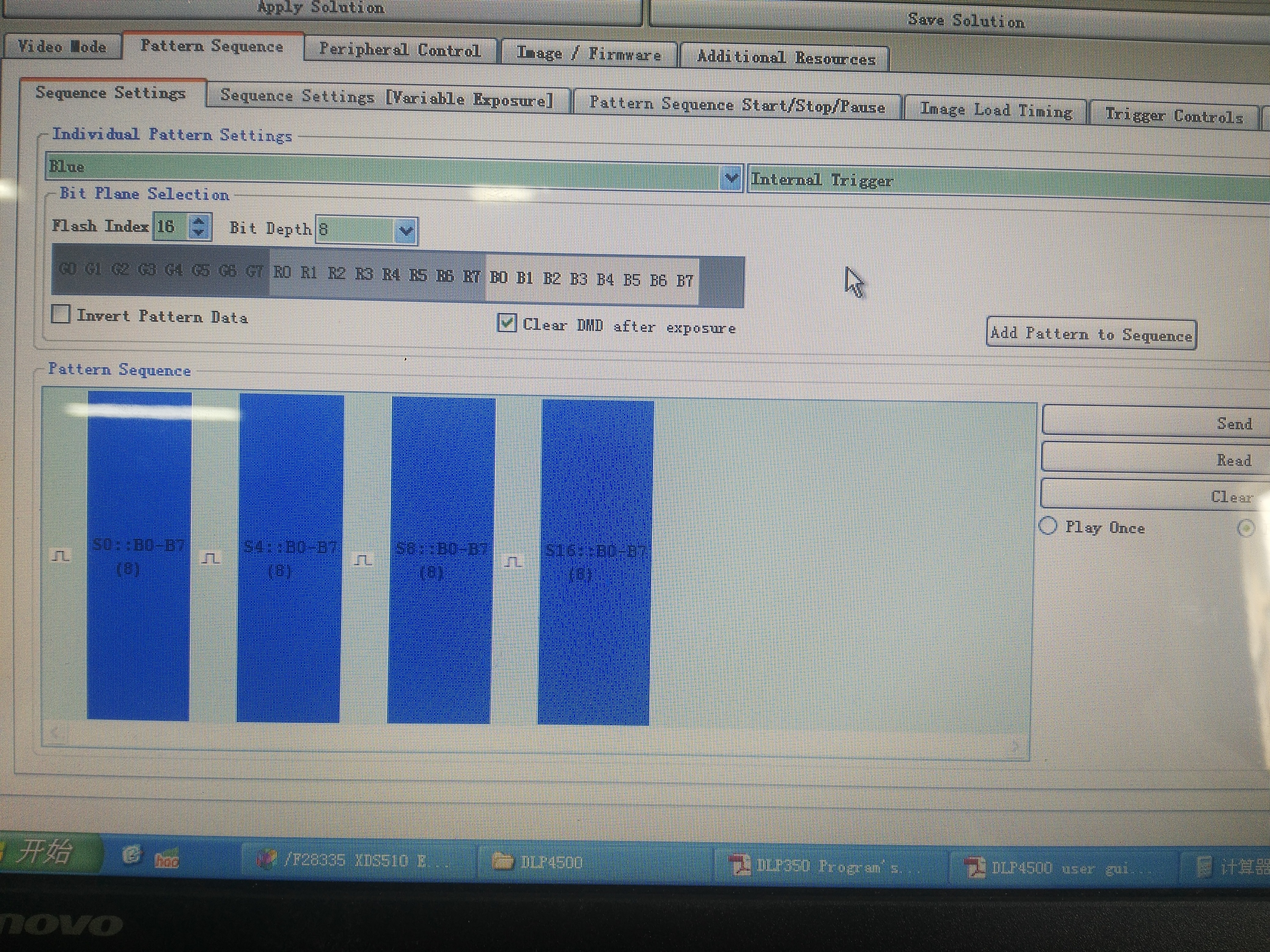
是内部触发还是外部?和pattern在Flash Image Index对应关系.选择什么色彩?(RGB LED ON)
曝光时间.
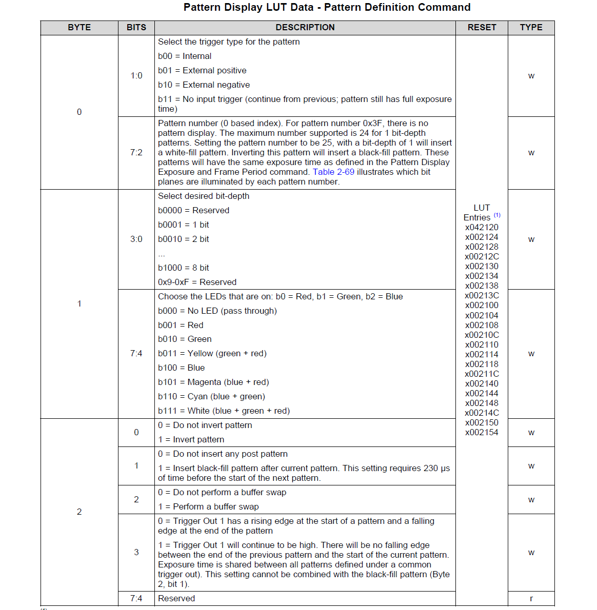
1. Byte 0, b1:0, choose trigger: internal (0x00), external positive (0x01), external negative (0x02), continue from previous (0x03) 2. Byte 0, b7:2, choose pattern number (what bit planes will be illuminated). Max is 24 for 1 bit-depth 3. Byte 1, b3:0, choose bit weight (1 to 8) 4. Byte 1, b6:4, choose which LEDs are on (blue, green, red) 5. Byte 2: (a) b0: Invert pattern if 1 (b) b1: Insert black pattern after current pattern if 1 (should be 0 if continuous trigger) (c) b2: Perform buffer swap if 1 (d) b3: Trigger out1 stays high (if this stays high for n patterns, then exposure time


