This thread has been locked.

If you have a related question, please click the "Ask a related question" button in the top right corner. The newly created question will be automatically linked to this question.

STL文件转换成.BMP文件

Other Parts Discussed in Thread: TIDA-00293

官方的DLP打印机是用什么软件将STL文件转换成.BMP呢?

  • 请参考:

    http://www.ti.com/tool/TIDA-00293

    • DLP 3D Printer User's Guide

  • 是用Freesteel Z-Level Slicer这个软件将stl文件切片成bmp文件吗?可以Freesteel Z-Level Slicer这个文件我安装好后就没有执行文件可以打开

  • 请参考切割指南:http://www.ti.com/lit/ug/dlpu025/dlpu025.pdf

    第8页,

    下载:

    http://www.freesteel.co.uk/wpblog/slicer/. The output image file format recommended is BMP.

  • 这个软件我安装了,根据网上提供的指令不能正常操作,不知道你们有没有将STL文件生成BMP操作的一些步骤指令能不能提供一下,列一个例子如何生成.bmp文件从头到结束如何输入指令能否列一下,谢谢

  • 请参考软件example:

    http://www.freesteel.co.uk/wpblog/slicer/

    Examples

    Cube10.stl

    solid block10
       facet normal 0 0 0
          outer loop
             vertex 0 10 10
             vertex 0 10 0
             vertex 0 0 10
          endloop
       endfacet
       facet normal 0 0 0
          outer loop
             vertex 0 0 10
             vertex 0 10 0
             vertex 0 0 0
          endloop
       endfacet
       facet normal 0 0 0
          outer loop
             vertex 10 10 10
             vertex 0 10 10
             vertex 10 0 10
          endloop
       endfacet
       facet normal 0 0 0
          outer loop
             vertex 10 0 10
             vertex 0 10 10
             vertex 0 0 10
          endloop
       endfacet
       facet normal 0 0 0
          outer loop
             vertex 10 10 0
             vertex 10 10 10
             vertex 10 0 0
          endloop
       endfacet
       facet normal 0 0 0
          outer loop
             vertex 10 0 0
             vertex 10 10 10
             vertex 10 0 10
          endloop
       endfacet
       facet normal 0 0 0
          outer loop
             vertex 0 10 0
             vertex 10 10 0
             vertex 0 0 0
          endloop
       endfacet
       facet normal 0 0 0
          outer loop
             vertex 0 0 0
             vertex 10 10 0
             vertex 10 0 0
          endloop
       endfacet
       facet normal 0 0 0
          outer loop
             vertex 10 10 10
             vertex 10 10 0
             vertex 0 10 10
          endloop
       endfacet
       facet normal 0 0 0
          outer loop
             vertex 0 10 10
             vertex 10 10 0
             vertex 0 10 0
          endloop
       endfacet
       facet normal 0 0 0
          outer loop
             vertex 10 0 0
             vertex 10 0 10
             vertex 0 0 0
          endloop
       endfacet
       facet normal 0 0 0
          outer loop
             vertex 0 0 0
             vertex 10 0 10
             vertex 0 0 10
          endloop
       endfacet
    endsolid
    

    Using Cube10.stl, which is a 10x10x10 cube

    > slice cube10.stl

    prints the JSON formatted result:

    {"xlo": 0.0, "yhi": 10.0, "xhi": 10.0, 
      "zhi": 10.0, "ylo": 0.0, "zlo": 0.0}
    {"n_triangles": 12, "n_points": 8, 
     "n_edges": 28, "n_unmatched_edges": 0}
    {"flat_area_z": [0.0, 10.0]}
    

    To create a single slice at Z=5 with a tool radius 1mm and layer height of 0.1,

    > slice -layer=0.1 -r1 -f0 cube10.stl

    The response (in JSOP) is:

    {"z": 5.0, "polygons": [{"points": [[-0.9078014184397163, -0.4194002678573765],
    [-0.911478589796249, -0.4113475177304966], [-0.9500634676302036, -0.312056737588
    6527], [-0.9771031917621306, -0.2127659574468086], [-0.9935408316398511, -0.1134
    7517730496448], [-0.9998993963780151, -0.014184397163120366], [-1.0, 0.085106382
    9787233], ..., [-0.792456004957226, -0.6099290780141844], [-0.
    8085106382978724, -0.5884815611038012], [-0.8597956319649682, -0.510638297872340
    3], [-0.9078014184397163, -0.4194002678573765]], "type": "core"}]}
    

    The shape of this is a square of width 12mm with 1mm rounded corners, because it is sampled with a disc of radius 1. If you want the cut on the surface, the shape must be offset back to its original form using -f-1.

    You cannot slice exactly on a flat area because the result is ambiguous, so slicer moves the position of Z slightly.

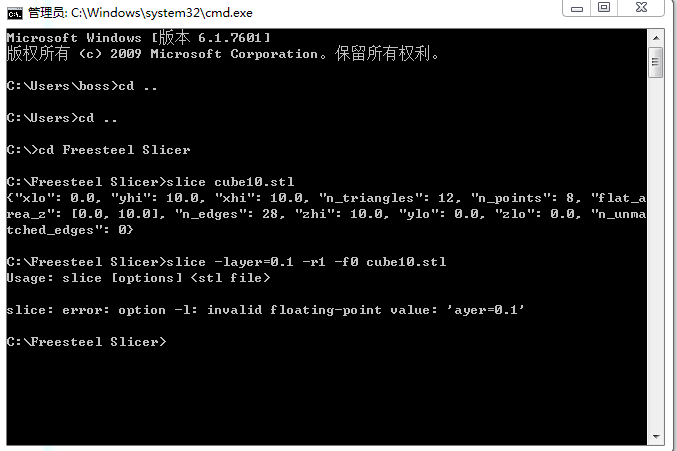
    > slice -z10 cube10.stl

    returns

    {"z":10.0075, "polygons": []}

    To create a silhouette, simply set the z value to below the zlo for the model and the layer thickness to greater than the height of the model.

  • 这个操作我也操作过了,不过在输入第二个指令时提示下面的错误

    这是什么原因呢?

  • 应该是-l 或 --layer

  • 如果我想输入bmp文件是不是输入:slice --output=*.bmp(*号为做任意的文件名称)是不是输入这条命令就可以了?可是我输入这条命令没有任何反应,是不是不是这样的?

  • 这是个第三方软件,你什么时候方便,和设计公司一起对你们培训一下.

  • 你好,如果这个要培训的话怎么安排,是要过去你们那边吗?还是通过网上视频操作呢?能不能让设计公司给出一个文档,将.STL文件输出为,bmp文件的一个使用说明呢?

  • 请告知邮件地址,我可以发给你的.

  • 你好,我的邮箱是linguimeng@sunsth.com

  • 和楼主遇到一样的问题,官方给我参考程序是错的, 应该是--layer 。

    但是仔细看了一遍之后我还是不知道怎么切片成BMP,而且还要固定分辨率的

  • 请问第八页cmd打开哪里是什么意思。。。是直接打开cmd输这些?还是cd转到安装文件夹?还是打开一个程序???

  • 可以给我一个成功切片成BMP的例子么,理论上去freesteel slicer 就可以切成固定的分辨率的bmp了。但是官方给的代码有问题的。希望有一个成功的例程。你之后给我PDF提到了4个软件,其中一个根本没用到,另一个是用来看z轴高度的。剩下两个那个CMD怎么出来的啊?是打开某个文件么,直接在cmd里输入是不行的啊

  • 下载和参考使用:

    www.freesteel.co.uk/wpblog/slicer/

  •   他这个是错的,我之前就是按照他这个来的。

  • 测试这个command lines,测试没有问题的.你也可以联系Freesteel Z-level slicer 供应商.

    @echo off

    set temp_path=NULL
    set object_file=NULL
    set output_path=NULL
    set /a layer_thickness=10
    set /a start_z_level=0
    set /a end_z_level=0
    set /a total_int=0

    :a
    set /p temp_path="Enter the path where the slicing program is installed(hit enter for default): "

    if "%temp_path%"=="NULL" (goto i) else (set slice_path="%temp_path%")
    set temp_path=NULL

    :i
    set /p temp_path="Enter the path where ImageMagick is installed(hit enter for default): "

    if "%temp_path%"=="NULL" (goto b) else (set im_path="%temp_path%")

    :b
    set /p object_file="Enter the path and file name of the object to be sliced: "

    if "%object_file%"=="NULL" (goto b)

    :c
    set /p output_path="Enter the path for the output images: "

    if "%output_path%"=="NULL" (goto c)

    :d
    set /p layer_thickness="What is the desired z-layer thickness (in microns)?: "

    if %layer_thickness% LSS 10 (goto d)

    :e
    set /p start_z_level="What is the beginning z layer?: "

    if %start_z_level% LSS 0 (goto e)

    :f
    set /p end_z_level="What is the ending z layer?: "

    if %end_z_level% LEQ %start_z_level% (goto f)

    if %layer_thickness% LSS 100 (goto g)

    %slice_path%\slice.exe -o %output_path%\0.bmp -r0.01 -w1290 -h806 -z%start_z_level%,%end_z_level%,0.%layer_thickness% -l0.%layer_thickness% --cavity=#000000 --core=#ffffff "%object_file%"

    goto h

    :g

    %slice_path%\slice.exe -o %output_path%\0.bmp -r0.01 -w1290 -h806 -z%start_z_level%,%end_z_level%,0.0%layer_thickness% -l0.0%layer_thickness% --cavity=#000000 --core=#ffffff "%object_file%"

    :h

    %im_path%\mogrify.exe -resize 912x1140! %output_path%\*.bmp

    Pause