

你好,
同一电路板上两个SN65HVD230互相通信测试,
第一片 RS引脚通过10k连接到GND,它连接CAN1
第二片RS引脚通过10k连接到3.3V,它连接CAN2
CAN1通过第一片SN65HVD230发数,
CAN2接收,示波器可以看到有数据过来,但是CPU无法正常接收,估计是校验没法通过。
这时把第二片RS引脚接地,CPU的CAN2可以正确收到CAN1的数据。
第二种情况,把CAN线,再连接一个USB转CAN的工具,到PC,打开这个工具后,工具能正常收数,这时CAN2也能正确收数,注意此时RS是10k电阻接3.3V的。
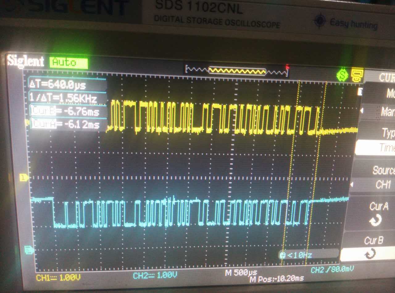
下图是两根CAN信号线,无法正常接收情况:
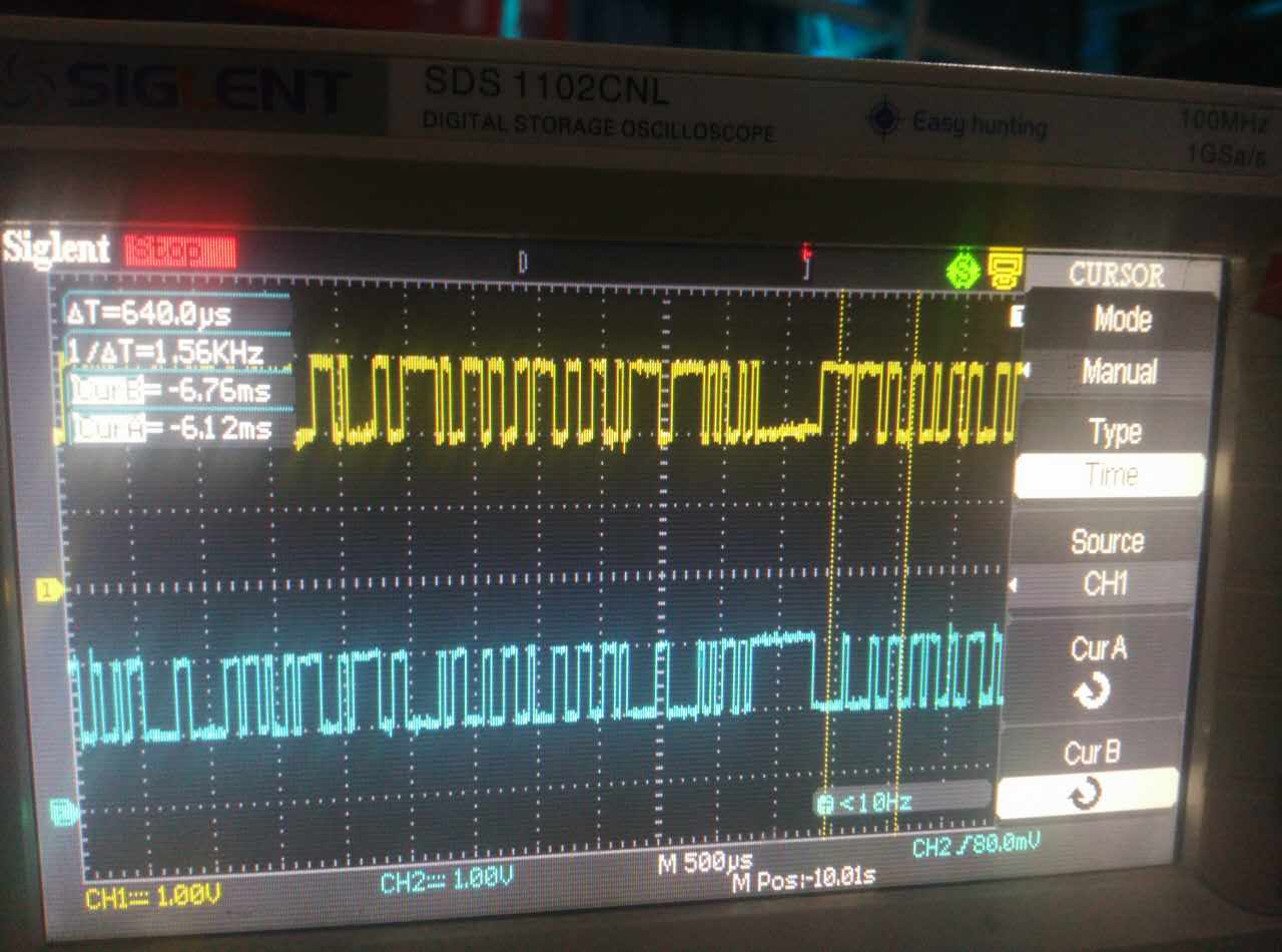
下图是可以正常接收情况:
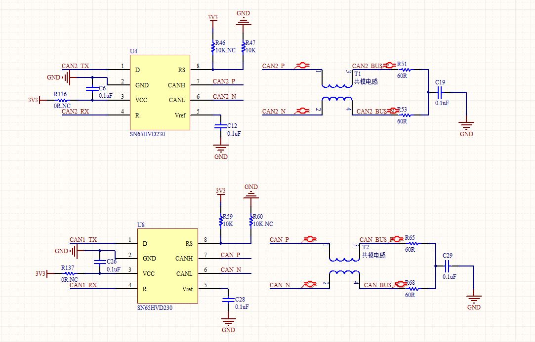
附加一份原理图:
希望得到帮助,谢谢!
