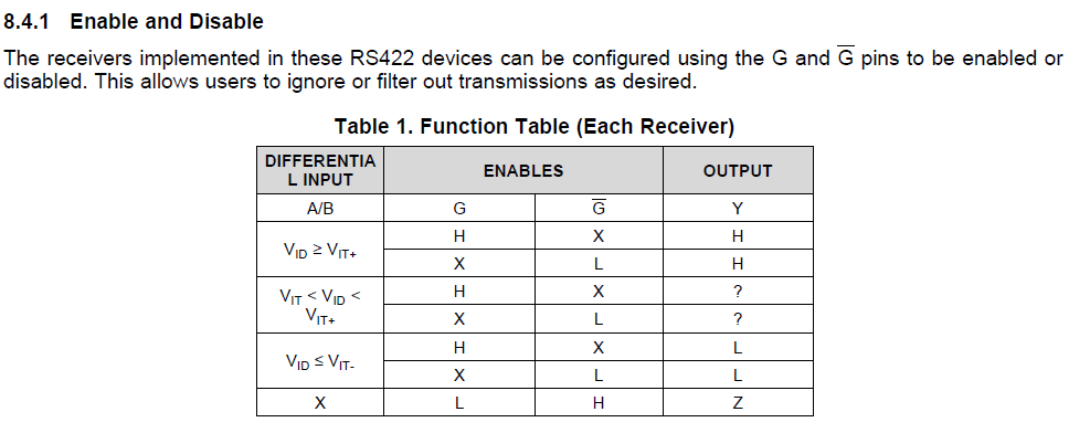
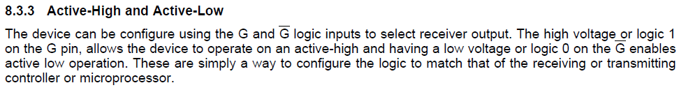
The device can be configure using the G and G logic inputs to select receiver output. The high voltage or logic 1 on the G pin, allows the device to operate on an active-high and having a low voltage or logic 0 on the G enables active low operation. These are simply a way to configure the logic to match that of the receiving or transmitting controller or microprocessor.
最近在使用AM26C32,发现datasheet中对于使能脚的描述,感觉和下面真值表有些冲突。请帮忙解答