This thread has been locked.
If you have a related question, please click the "Ask a related question" button in the top right corner. The newly created question will be automatically linked to this question.
Part Number: TDES954Other Parts Discussed in Thread: TSER953,
现在想实现:使用MCU的GPIO输出高低电平给TDES954的GPIO,然后通过同轴电缆到TSER953对应的GPIO输出高低电平。
1)上述想法是否可以实现?
2)若可以实现,如何配置寄存器?
您好,您的意思指的就是GPIO透传的特性。
那么对于TDES954来说,配置GPIO为input,对于TDES953的GPIO 配置为output就可以了。
比如954配置GPIO为input的寄存器0X0F。同样,对于953来说,GPIO配置为输出,可以去数据手册里去找对应的寄存器配置,另外,就是pass through all enable。
可以具体一些吗?都需要配置
void  v3link_init(void)
{
   /* 954 config */
   ti954_write(0x01, 0x01); /* reset */
   delay_ms(50);
   ti954_write(0x4C, 0x01); /* select port 0, depend on the hardware */
   ti954_write(0x58, 0xda); /* i2c pass-through non sync */
   ti954_write(0x0F, 0x7F);

   /* ti953 i2c address */
   ti954_write(0x5B, 0x30);
   ti954_write(0x5C, 0x30);

   /* tpl0102 i2c address */
   ti954_write(0x5D, 0xA0);
   ti954_write(0x65, 0xA0);

   /* set i2c clock 400MHz */
   ti954_write(0x0A, 0x13);
   ti954_write(0x0B, 0x25);

   ti954_write(0x0C, 0x01); /* enable port0 */

   ti954_write(0x20, 0x20); /* forwarding enabled for RX Port 0 */
   ti954_write(0x33, 0x03); /* 4 lanes */

   ti954_write(0x6d, 0x7c); /* set CSI Mode(ti953 compatible) */


   /* 953 config */
   ti953_write(0x01, 0x02); /* reset */
   delay_ms(50);
   ti953_write(0x02, 0x73); /* 4 lanes,continuous clock */

   ti953_write(0x32, 0xe9); /* back channel configuration */

   /* set i2c clock 400MHz */
   ti953_write(0x0B, 0x13);
   ti953_write(0x0C, 0x26);

   /* config gpio */
   ti953_write(0x0E, 0xF0); /* gpio output enable */

   ti954_write(0x58, 0xfe); /* i2c pass-through sync */
   ti953_write(0x03, 0x08); /* mode syn */
}
上面是初始化配置,可以帮忙看下吗?我按照你说的配置没有实现。
透传GPIO的步骤:
比如您打算使用954的GPIO3,那么953也使用GPIO3去对应。
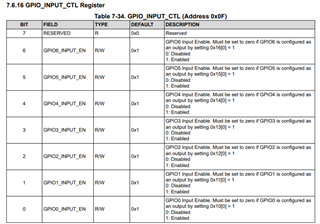
1. 配置954的GPIO3作为输入,通过配置寄存器0x0F[3]=1,GPIO3 input enable,同时0x13 bit[0]=0, disable GPIO3 output.
2.配置953的GPIO3 作为输出,通过配置寄存器0x0E[7]=1, GPIO3 output enable.同时0X0E的bit[3]=0 disable GPIO3 input.
现在没有成功,体现在什么地方?MCU的GPIO高低电平 ,953的GPIO输出什么电平,一直为low还是其他情况?
MCU的GPIO如初1秒切换的高低电平,确认给到954的引脚上了(电平为1.8V,GPIO3),然后做了如下配置,/* ti954 gpio */ti954_write(0x0F, 0x7F);ti954_write(0x13, 0x00);/* ti953 gpio */ti953_write(0x0E, 0xF0); 此时测量953的GPIO3,发现始终是低电平。
测试发现监测954的0x0E寄存器会随MCU的电平变化实时变化,而953的0x53寄存器始终是0.即便我把相应引脚拉高。
偶,953的0x53寄存器只监测输入。
我上面是举例使用GPIO3进行透传,实际电路您也是将MCU的GPIO 接到954的GPIO3上是吗?另外需要注意GPIO是OD输出,需要上拉4.7K电阻到VDDIO。
检查下954的GPIO3是否已经上拉?