This thread has been locked.

If you have a related question, please click the "Ask a related question" button in the top right corner. The newly created question will be automatically linked to this question.

DS90UB948-Q1: 地址为0xA2的寄存器值变化了,在规格书找不到,实际能读到这个基础器的值

Part Number: DS90UB948-Q1

hello,

Problem description: We use a product of the deserializer DS90UB948-Q1. When the customer uses it, the picture flickers.

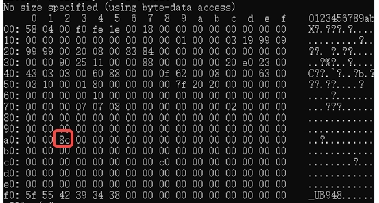
When the problem occurs, by reading and printing the value of the 948 register, compared with the normal 948 register value,

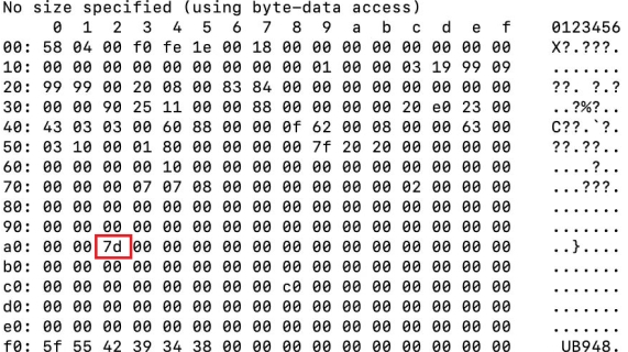
only the register value of the address 0xA2 has changed, from 8c to 7d.

Screenshot of normal value:

Screenshot of abnormal value:

1.Why can't I find this register 0xA2 in the specification? 

2.What does the change of this value mean?

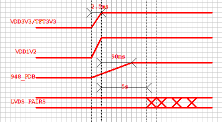
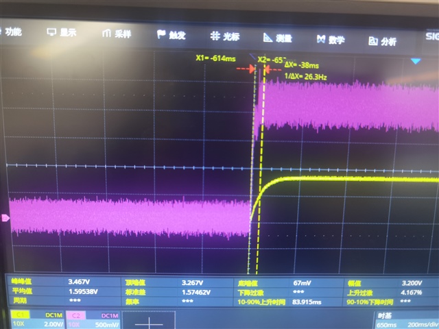
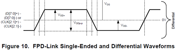
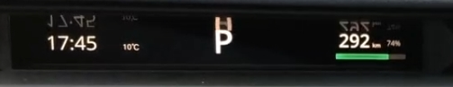
3.Could the accidental phenomenon in the figure below be possible that the signal is interfered,Can it be solved if the output voltage swing is increased?

Output voltage swing configuration register 0x4B is 0

thanks!

  • 您好,0XA2确实没有这个寄存器的介绍,所以可能无法通过这个寄存器的改变来分析。

    那么针对您目前的问题,我的建议是在屏幕闪烁的时候,看下是否能正常lock?如果不能,建议在948做一下margin analysis。

    同时作为debug调试的话,看下缩短serializer和deserializer之间的距离,是否有所改善。

  • dear Kailyn Chen,

    After the screen flicker problem occurs, it cannot be restored to normal. It needs to be powered on again to restore normal. Reading the register value LOCK is normal. The probability of this problem is very small and this phenomenon cannot be reproduced on the desktop. It is not good to determine whether the improvement is made by shortening the connection harness between the deserializer and the serializer.

    1.Output voltage swing configuration register 0x4B is 0. The default setting is minimum output. Is it necessary to try increasing the output?

    2.Connect the probe of the oscilloscope to the D2 ± and CLK2 ± signal lines and apply interference with the walkie talkie. The image may exhibit similar flicker, but after removing the interference, it returns to normal. Is this abnormality possibly related to interference on the openLDI output signal line.

  • 1.Output voltage swing configuration register 0x4B is 0. The default setting is minimum output. Is it necessary to try increasing the output?

    I think the flicker is not related to the output swing. 

    Connect the probe of the oscilloscope to the D2 ± and CLK2 ± signal lines and apply interference with the walkie talkie. The image may exhibit similar flicker, but after removing the interference, it returns to normal. Is this abnormality possibly related to interference on the openLDI output signal line.

    It looks like the  interference is related  to the OLDI output, I need to check it again and reply you later. 

  • Dear Kailyn Chen:

    1. Copy that!But, when the interference is removed, it can return to normal.The image flickering phenomenon on the vehicle cannot be self recovered, and the system needs to be restarted to recover.

    2.D2+/-transfer HS SYNC,VS SYNC and data DE,If the oscilloscope probe is not connected to the signal line, interference with the interphone will not flicker.When the interference is removed, it can return to normal. It looks like one of the serializer output or 948 output, and TFT LCD display terminals is abnormal.

  • Are you using single or dual OLDI at the 948 output? Once flickering, if you apply a digital reset (register 0x01[0]) on the 948, will that recover the issue?

    It looks like one of the serializer output or 948 output, and TFT LCD display terminals is abnormal.

    Which serializer do you use?  I think we should decide the flicker source, if it is from serliazer or deserializer?

    In addition, when does appear flicker? Does the flickering start immediately upon powerup?

    Or if possible, could you please try to change another cable which has low insertion loss ? 

  • Dear Kailyn Chen:

    1.We used single OLDI at the 948 output,The next time this phenomenon occurs, the tester uses unload to reload 948, but this way the operating system will control the power off of 948 and power it back on.

    2.Serializer is used DS90UB949,The flicker source has not been found so far.

    3. The flickering was start immediately upon powerup and extremely low probability,we have not yet tried to change another cable for testing.

    4.The register specification with address 0xA2 is not defined, but values can also be written inside without causing exceptions.

  • What about the power up sequence? An incorrect power up sequence could cause issues. Please confirm the power up sequence about the datasheet P93:

    https://www.ti.com/lit/ds/symlink/ds90ub948-q1.pdf

    In addition, are you convenience to use the MAP tool to do the Margin Analysis? 

  • We didn't use the MAP tool to do the Margin Analysis. 

    The power-on sequence of the system is shown in the following figure:

  • Hello, there is no problem about the power up sequence. But  notice that  the DS90UB948Q-Q1 should be powered up after a compatible Serializer has started sending valid video data, that to say, we should provide valid data from a compatible Serializer before power-up, that is the t5 time. 

    .If this condition is not satisfied, then a digital (software) reset or hard reset (toggling PDB pin) is required after receiving the input data. Please confirm this.


  • The LOCK pin only becomes high a few seconds after the PDB becomes high.

    The timing diagram between the PDB and the input RIN+/- signal is shown below:

    1.Is it necessary to digitally reset the PDB after it becomes high? Which is t4 time.

    2.Since the value of 0xA2 has changed from 8c to 7d after reading the 948 register after the screen flickers,

    and the specification does not actually define 0xA2. Can we use this value change to determine when a

    digital reset or hardware reset is required to restore normal?

  • 1.Is it necessary to digitally reset the PDB after it becomes high? Which is t4 time.

    If DS90UB948Q-Q1 should be powered up after a compatible Serializer has started sending valid video data, there is no need to do the digital reset. Instead, you should do the reset to prevent DS90UB948 lock the noise signal.

    Since the value of 0xA2 has changed from 8c to 7d after reading the 948 register after the screen flickers,

    and the specification does not actually define 0xA2. Can we use this value change to determine when a

    digital reset or hardware reset is required to restore normal?

    Yes, that is what I want to know, but I didn't find anything about the 0XA2 register, so I'd like to confirm again about  this, as it didn't describe the 0XA2 in datasheet. Once I confirm this question, I will reply you. 

  • Hi, sorry to reply you so late, I need to confirm with you about the below questions. 

    1. How many ICs and Systems do you see this failure on?
    2. Have you done ABA swap to the suspect IC and does the failure follow the IC from a known good system to another system and vise-versa.
    3. Does the screen actually flicker or is it just an offset of colors ?
    4. VOD 0x4B = 0x0 is low the default value should be 0x8 
    5. When you see the flickering screen does the lock signal flicker as well?

    Regards,

  • Hello,

    About the 0XA2 register, I have confirmed with senior engineer and please for you reference:

    0xA2 is a reserved register. We use it to set the internal always-On CLK (AON) to a specific range.
    This should not effect video performance. Basically, regardless of register 0xA2 value, if your system uses an external CLK, then AON value doesn't matter, it should be irrelevant to the video performance since your video is driven by an external CLK source. 

    If this issue is only happening on a single IC can you please do ABA swap to see if the issue follow the suspect IC when putting it on a known good system and vise-versa ?

  • dear  Kailyn:

    1.There are three systems have this failure had  occurred.

    2.The suspicious IC has not been swapped yet, which is a very unlikely fault phenomenon, even if swapping is difficult to replicate during testing on the desktop.

    3.there is only screen flickering and no offset of colors.

    4.The output voltage swing (differential)Vodp-p setting is generally 350mV,I need to check the register values with my colleagues.

    5.The faults were all caused by the complete product installed on the vehicle, and there was no test lock signal, so it is not known.If there is any jitter in the signal when tested on the countertop late.

  • dear  Kailyn:

     Copy that! I will test the prototype to see if it can reproduce the phenomenon before making a replacement.

  • I will test the prototype to see if it can reproduce the phenomenon before making a replacement.

    OK ,Does the failure follow the 948 IC ?  waiting for your feedback.