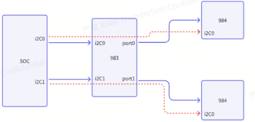
DS90UB983-Q1: 983 and 984 link failed

Part Number: DS90UB983-Q1

1. What is the difference between i2c1 and i2c2 of the device, and why does i2c1 read the register state differently than i2c2?

2. Now we use 983 with 984. After direct power-on, 983 cannot read the link status, nor can we read the i2c address of 984. May I ask, isn't link handshake successful by default after 983 and 984 are powered on?

thanks!

  • 1  I usually only use iic0 and haven't used iic1 or iic2. However, according to the manual, these IICs are all the same, personal understanding. The read content is different because these IICs are already independent (they choose different register copies based on different port_dels)

    2  To ensure that 983 and 984 operate at the same link rate, such as whether they are both 10.8GB

  • note   register     PORT_SEL

  • Thank you for your reply.

    The actual register state read by i2c is not the same, for example, i2c0 sets the local register 0x07 to 0x80, but i2c1 reads 0x07 to a different value. How can this i2c1 be set to the same state as i2c0?
    At the same time, we found that an MCU is attached to the i2c bus on the 984 side. At this time, i2c0 can access this device, but i2c1 cannot access it. How to make i2c1 also access this device?

    What do you need to configure if 983 drives two 984?
    Also 984 how to choose dp0 output screen?

  •   maybe you should pay attention to  register  PORT_SEL

    。。。。。  I dont know how to use i2c1 to access  984

  • Who is the customer for this case?

    1. What is the difference between i2c1 and i2c2 of the device, and why does i2c1 read the register state differently than i2c2?

    The 983 has three different I2C buses to allow for parallel access to local device registers and to allow up to 24 I2C target addressing. Some registers will read different depending on the I2C port that is used to differentiate the I2C buses.

    2. Now we use 983 with 984. After direct power-on, 983 cannot read the link status, nor can we read the i2c address of 984. May I ask, isn't link handshake successful by default after 983 and 984 are powered on?

    Without knowing the background of this system, I cannot give a definitive answer as to why the link is not successful upon power up.

    Can we get answers to the following questions?

    • Is the device operating in FPD3 or FPD4 mode?
    • If the device is operating in FPD4 mode, what link rate are the 983 and 984 strapped to?
      • This is determined by MODE_SEL settings
    • Is the customer running a script on the 983 or 984?
    • Has the customer already confirmed that the channel specifications are met?
      • Has this system already been validated before? Are there other systems where link is successful?
  • Using FPD4, we have achieved link sucess through debugging, and access to 984 through i2c2, but cannot access other devices hanging on the 984 i2c bus, may I ask how to set up i2c2 to access the external i2c device

  • If you are trying to direct an I2C transaction from the SER to one of the two I2C ports on the 984, the DEST_ADDR[2:0] field in the DESTINATION_FIELDx registers. 984 Datasheet section 6.5 covers this programming.

    Can you provide a diagram of the customer's system for context? With a diagram, I can help with programming the registers for I2C communication.