This thread has been locked.

If you have a related question, please click the "Ask a related question" button in the top right corner. The newly created question will be automatically linked to this question.

TIDA-01605: A little confused about the Two-Level Turnoff Protection

Part Number: TIDA-01605

Hi!

I have some questions about the Two-Level Turnoff Protection.

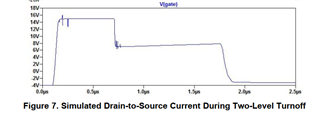
First, Equation 15 shows the voltage of first-level turnoff is 11.9V, why do the Bottom graph of Figures 7 and 8 show around 8V?

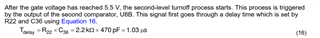
Second,  why gate voltage reached 5.5 V and the second-level turnoff process would starts? This gate volatage refers to the Q1 or the SiC MOSFET?

  • 您好,

    公式15算的是G2到-4Vb之间的电压, Figures 7 and 8 底部曲线是 SiC MOSFET的gate-to-source  之间电压,参考点不一样

    我理解的是这里的5.5 V电压应该是根据R22 and C36延迟时间估算的吧,也就是说第一级关断保护后R22C36延迟时间常数后,就会启动第二级关断保护

      这里的gate volatage应该指SiC MOSFET的

  • 您好,感谢您的回复,

    但我还是有些不解,我认为公式15最终得到的电压应该是以s2为基准的电压(0V),因为它在最后减了4V。G2输出为15V,与(-4V)的压差为19V,经过R13和R10的分压后为15.9V,之后再减去4V应该就是以0为基准的电压吧。这是我的理解,如有错误,希望能得到您的指导。

    关于第二个问题,我不明白为什么会到达5.5V。在R22和C36的延迟阶段,此时SiC MOSFET的gate-to-source  之间电压难道不是固定在了第一级关断电压附近么,要么是11.9V,要么是图上所画的8V左右(源于第一个问题),为什么还会下降呢?

    期待着您的回复,谢谢。