Part Number: TXB0304
Other Parts Discussed in Thread: TS3A27518E, SN74AXC4T774, SN74AXC8T245
Hi Sir,
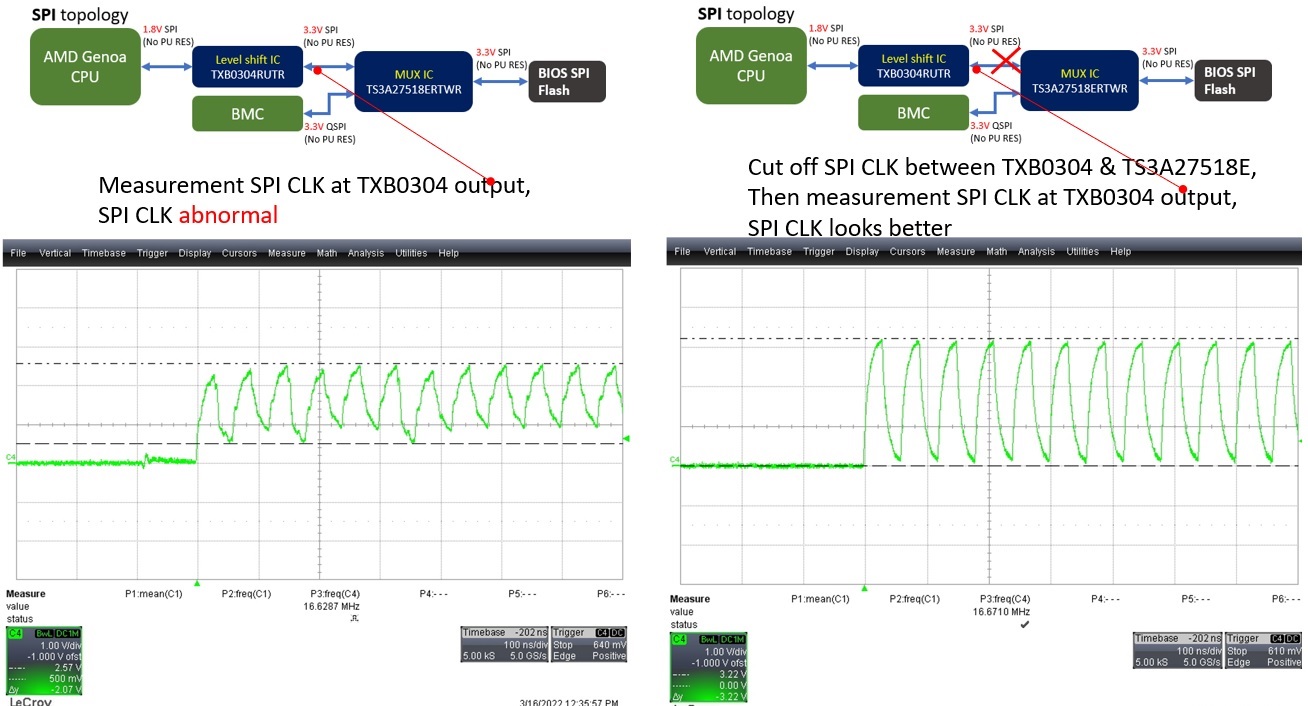
Please ref attach pic.
In our SPI topology CPU(1.8V) <=> TXB0304 <=> TS3A27518E(3.3V), SPI CLK is abnormal at TXB0304 output.
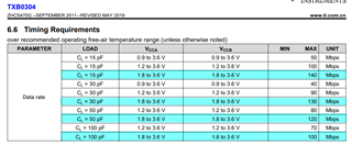
If we cut off SPI CLK between TXB0304 & TS3A27518E, then measurement at TXB0304 output side, it looks normal.
Ref application note Effects of pullup and pulldown resistors on TXS and TXB devices (Rev. A) (ti.com), section "1.3 TXB Pullup and Pulldown Resistor Analysis":
Check abnormal waveform, it looks like there is PU & PD at TXB output side to TS3A27518E, then cause output Vol & Voh not at 0V & 3.3V,
but actually, our design is without PU/PD RES.
1. Check TS3A27518E datasheet, I can't find PU or PD data in datasheet, can you double check?
2. Do you have any comment for this issue?
Thanks~