Part Number: SN74LVC1GX04
hi TEAM:
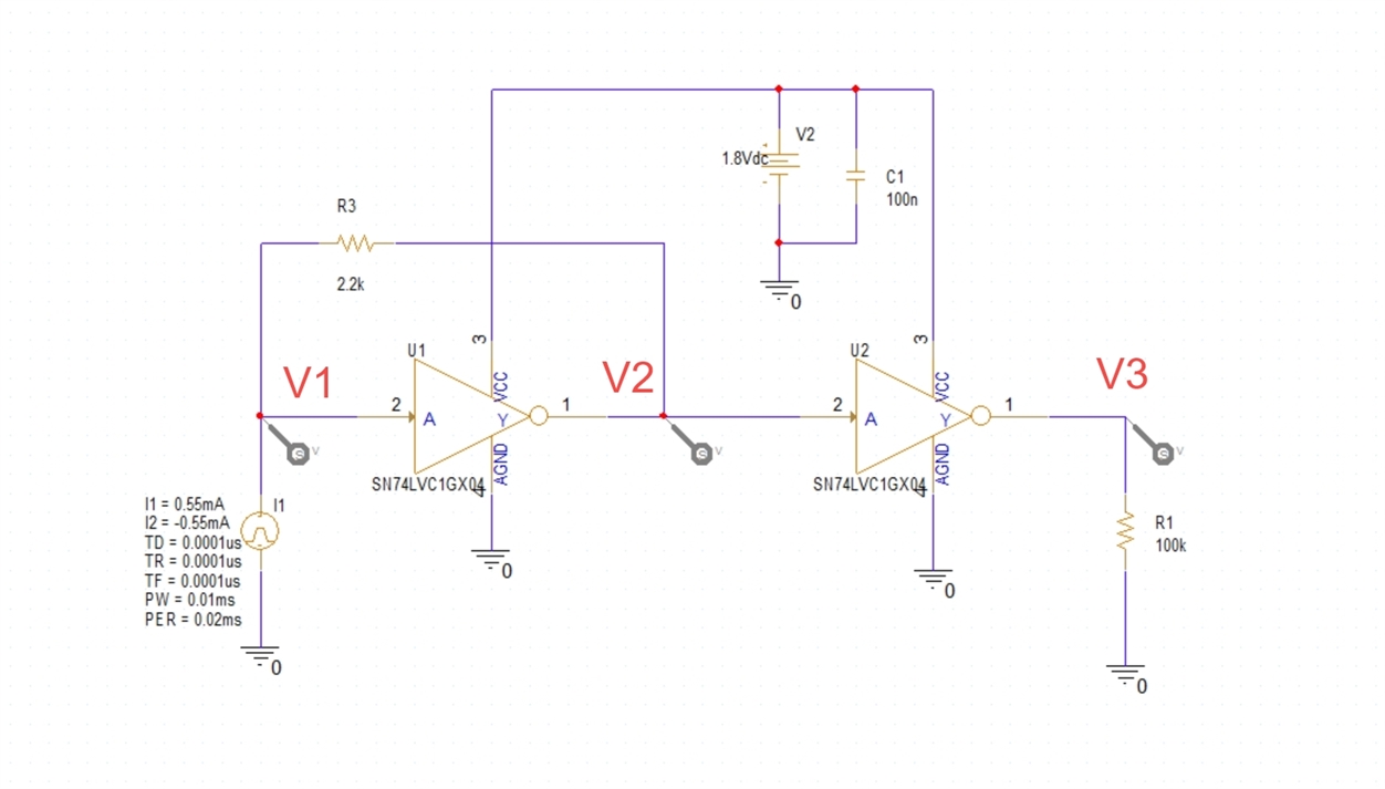
我们用两个SN74LVC1GX04用作电流(+0.55mA/-0.55mA)转电压(0/1.8V)用途,仿真设计如下

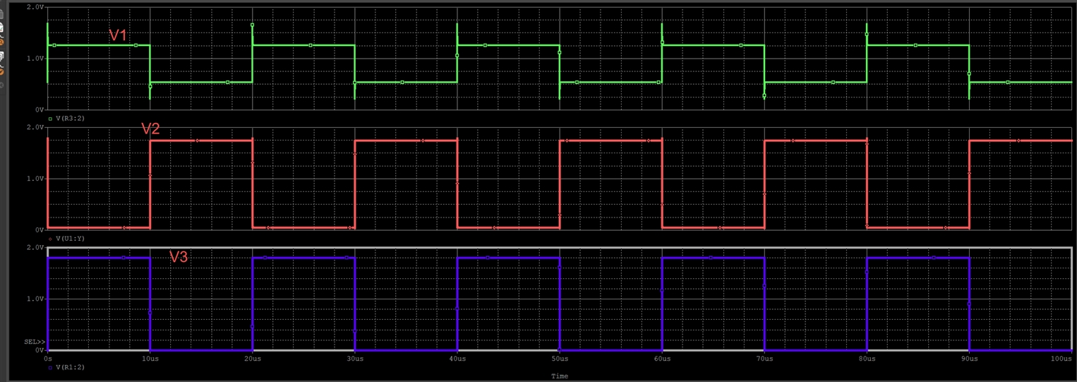
对应仿真结果电压如下,达到了设计目的:

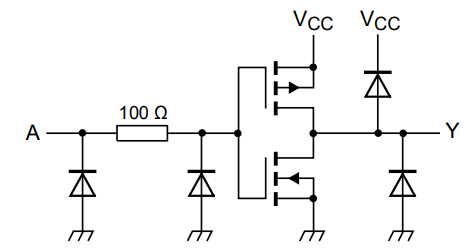
但是如果一个inverter内部逻辑如下(由两个mosfet组成),那么仿真图中V1上的电压是如何来的呢?V2有没有可能处在inverter的VIL和VIH之间?

This thread has been locked.
If you have a related question, please click the "Ask a related question" button in the top right corner. The newly created question will be automatically linked to this question.
Part Number: SN74LVC1GX04
hi TEAM:
我们用两个SN74LVC1GX04用作电流(+0.55mA/-0.55mA)转电压(0/1.8V)用途,仿真设计如下

对应仿真结果电压如下,达到了设计目的:

但是如果一个inverter内部逻辑如下(由两个mosfet组成),那么仿真图中V1上的电压是如何来的呢?V2有没有可能处在inverter的VIL和VIH之间?

您好
感谢您对TI产品的关注!为更加有效地解决您的问题,我们建议您将问题发布在E2E英文技术论坛上(https://e2e.ti.com/support/logic-group/logic/f/logic-forum),将由资深的英文论坛工程师为您提供帮助。